Medical examination and/or treatment device
阅读说明:本技术 医学的检查和/或治疗设备 (Medical examination and/or treatment device ) 是由 M.阿津杰 S.格罗斯 N.赫尔曼 于 2015-05-21 设计创作,主要内容包括:一种医学的检查和/或治疗设备(1,29),其包括具有可多轴移动的臂(3,31)的机器人(2,30);设置在该臂(3,31)上的C形臂(4);用于给C形臂(4)供电的电缆(5,32);器件,该器件用于在C形臂(4)移动时使电缆(5,32)跟随;其中所述器件设置在机器人(2,30)上或者设置在机器人(2,30)的部件上。(A medical examination and/or treatment device (1,29) comprising a robot (2,30) with a multi-axis movable arm (3, 31); a C-arm (4) arranged on the arm (3, 31); a cable (5,32) for supplying power to the C-arm (4); means for following the cable (5,32) when the C-arm (4) moves; wherein the device is arranged on the robot (2,30) or on a component of the robot (2, 30).)
1. A medical examination and/or treatment device (1,29) comprising:
-a robot (2,30) with a multi-axis movable arm (3, 31);
-a C-arm (4) arranged on the arm (3, 31);
-a cable (5,32) for powering the C-arm (4);
-means for following the cable (5,32) when the C-arm (4) is moved;
characterized in that the device is arranged on the robot (2,30) or on a component of the robot (2,30), wherein the device is designed as a telescopic tractor (6,21,23) with a plurality of telescopic parts (7,17,18,19,27), one of which is arranged on the arm of the robot and the other of which is connected to a cable, wherein at least one of the telescopic parts (7,17,18,19,27) of the telescopic tractor (6,21,23) has a drive.
2. Medical examination and/or treatment device according to claim 1, characterized in that the means are arranged on a multi-axially movable arm (3, 31).
3. Medical examination and/or treatment device according to claim 1, characterized in that the drive is designed as a rotary motor, a linear motor, a motor unit with a traction screw, a hydraulic cylinder or a pneumatic cylinder.
4. A medical examination and/or treatment device according to claim 1, characterised in that the telescopic retractor (6,23) has a balancing mass (16,28) which, when the telescopic retractor (6) is moved, can be moved in the opposite direction to the movement.
5. A medical examination and/or treatment device according to claim 4, characterised in that the balancing mass (16,28) is coupled to the telescopic element (7) via a traction element.
6. A medical examination and/or treatment device according to claim 1, characterized in that at least one of the telescopic elements (18) of the telescopic retractor (21) has a surrounding retractor element which is coupled on one side to the first telescopic element (17) and on the opposite side to the second telescopic element (19).
7. A medical examination and/or treatment device according to claim 1, characterised in that the cable (5) is arranged on the component by means of at least one holding element (9, 10).
8. A medical examination and/or treatment device according to claim 1, characterised in that the cable (5) is accommodated in a hose or a sleeve.
Technical Field
The invention relates to a medical examination and/or treatment device comprising a robot having a multiaxially movable arm, a C-arm arranged on the arm, a cable for supplying power to the C-arm, and means for following the cable when the C-arm is moved.
Background
Such a device, known as "ARTIS Zeego", is manufactured by the applicant. It relates here to a robot for angiographic applications, having a multi-axially movable arm supporting a C-arm. The cable connected to the C-arm contains data lines, control lines and lines for power supply. In such conventional medical devices, the arm of the robot has a plurality of through-openings through which the cables are guided. The cable is terminated in a cable storage, which is usually mounted on the ceiling. When the robot moves, the length of the cable increases, and therefore the cable is pulled out from the cable storage. When the C-arm of the robot then moves back again into the initial position, the cable is then pulled into the cable storage again under the action of the elastic element.
Since such medical examination and/or treatment devices have a wider range of movement possibilities than industrial robots, it can be difficult to follow the cables accordingly.
Disclosure of Invention
The object of the present invention is to provide a medical examination and/or treatment device which makes it possible to achieve a wider range of movement possibilities of the C-arm.
In order to solve the problem, according to the invention, in a medical examination and/or treatment device of the type described above, it is provided that the means are arranged on the robot or on a component of the robot.
The basic idea of the invention is that in conventional devices the cable store arranged on the ceiling is replaced by a device arranged on the robot or on a component of the robot. The device is designed to follow the cable or to provide a longer desired length of cable when the C-arm is moved. In this way, the cable storage can be omitted, since the additional length required for the cable can be provided directly on the robot. The advantage thereby results that the cable can follow around a plurality of axes in all conceivable movements without the restrictions caused by ceiling-mounted cable stores or ceiling-mounted cable rollers. This has the advantage that the cable or the additional length thereof required for movement can be moved faster, so that the movement speed of the multiaxially movable robot arm can also be increased. It is important that the provision of the additional length required for the cable to move is no longer carried out in the cable storage mounted on the ceiling, but directly on the robot, in particular on the multi-axis movable arm.
According to a first embodiment of the invention, the device is designed as a telescopic retractor with one or more telescopic elements. In the simplest case, the telescopic retractor has only one telescopic part, which can be moved linearly, whereby the cable follows when the C-arm is moved. The required follow-up of the cable, which is necessary when the C-arm is moving, can be performed by operating the telescopic member of the telescopic retractor. In order to further improve the following-up, it is provided according to the invention that the telescopic retractor has a plurality of telescopic parts. For example with two or three telescopic parts that can be moved relative to each other. One telescopic part is arranged on the robot or on an arm of the robot, and the other telescopic part is connected with a cable.
In order to increase the user-friendliness, at least one telescopic element of the telescopic retractor has a drive. By means of such a drive, the telescopic retractor can be driven, whereby the medical examination and/or treatment device can be automatically adjusted. It is also obviously possible according to an embodiment of the invention for all the telescopic parts of the telescopic retractor to have a drive. It is particularly preferred in one variant that two or more telescopic elements are kinematically coupled to one another, so that when one of the telescopic elements is operated, the other or further telescopic elements are likewise operated, i.e. moved. By this measure, the speed of movement of the telescopic retractor and thus of the cable can be increased.
Within the scope of the invention, it is provided that the drive is designed as a rotary motor or a linear motor or as a motor unit with a traction screw, a hydraulic cylinder or a pneumatic cylinder. All mentioned drives are capable of moving the telescopic retractor.
According to the invention, the telescopic retractor preferably has a balancing mass which can be moved in the opposite direction to the movement of the telescopic retractor when the telescopic retractor is moved. By means of the balancing mass, a mass balancing can be achieved, whereby excessively high forces in the cable can be avoided. In particular, gravity can be compensated for by means of the balancing mass as a function of the angle of inclination. It is also obvious that a plurality of telescopic elements of a telescopic tractor can be provided with a balancing mass. The balancing mass is thereby always displaced in the opposite direction to the telescopic retractor or its telescopic part, whereby changes in the weight distribution caused by the extension or retraction of the telescopic part can be automatically compensated.
In this connection, it is particularly preferred if the balancing mass is connected to the telescopic retractor by means of a retractor. The traction means can be designed as a belt or chain, so that the balancing mass can also be displaced during the movement of the telescopic means by means of a kinematic coupling by means of the traction means. In the reverse movement, for example when the telescopic part is pulled in the retracted position, the balancing mass likewise moves in the opposite direction.
In the medical examination and/or treatment device according to the invention, at least one of the plurality of telescoping parts of the telescopic retractor has a surrounding pulling element which is coupled on one side to the first telescoping part and on the opposite side to the second telescoping part. The traction means is designed here as a continuous belt which runs over two spaced rollers. The telescoping member may be located on the upper return section and the counterbalance mass may be located on the lower return section.
Another variant of the invention provides for the telescopic retractor to be equipped with a damping element for damping the movement of the telescopic part. In particular, undesirable vibrations or shocks which may adversely affect the imaging device should be damped. The damping element can be designed, for example, as a viscous damper.
Within the scope of the invention, the telescopic element has one or more damping end stops. Mechanical shocks or vibrations are thereby avoided when the telescopic element reaches the end stop. Interference in the imaging device can also be avoided by this measure.
In a telescopic retractor with a plurality of telescopic elements, all telescopic elements are preferably operated simultaneously. In this way, the position of the cable can be fixed at any time.
According to an alternative embodiment of the invention, the device is designed as a hinge having at least two hinge sections. A hinge is provided instead of a telescopic retractor, which hinge is connected on one side to the robot, in particular to the arm of the robot, and on the other side to a cable. At least two hinge sections can be rotated relative to each other in the movement plane, so that the distance between their free ends changes between zero and the total length of the two hinge sections. Because the cable is connected to one end of the hinge, it follows by the movement of the hinge. When the C-arm is moved by a multiaxially movable arm movement (which usually has a plurality of articulated, movable sections), the cable is followed by a corresponding movement of the hinge having at least two hinge sections. If appropriate, the hinge can also have more than two hinge sections, for example three or four hinge sections, thus forming a scissor-like hinge or a folding-rule-like hinge. By selecting a hinge with a length adapted to the hinge section, the required follow-up of the cable can however also be performed by a hinge with two hinge sections.
It is also conceivable that the hinge has at least one spring element for generating a restoring force in the medical examination and/or treatment device. After the hinge has been moved into the open position, the spring element can also pull the hinge or its hinge sections back into the initial position again. In the open state, a stop of the hinge is possible.
In order to increase user friendliness, the hinge can have at least one drive. Similarly to the drive for the telescopic extension, the drive for the hinge can be designed as a rotary motor or a linear motor or as a motor unit with a traction screw, as a hydraulic cylinder or as a pneumatic cylinder.
In both variants of the invention, i.e. in the telescopic retractor and in the hinge, the cable is arranged on the device by means of at least one retaining element. In one case, the retaining member is mounted on the telescopic retractor, and in the other case the retaining member is provided on the hinge.
The cable of the medical examination and/or treatment device is preferably accommodated in a hose or a sleeve. Since the hose or cannula does not contact other parts of the device, virtually no wear occurs, which is advantageous for use in a sterile treatment room. Another advantage is that the cable contained in the hose or sleeve is easy to clean when needed, thereby meeting the hygienic requirements for applications in the medical field.
Drawings
Further advantages and details of the invention are explained below with reference to the figures in connection with embodiments. The drawings are schematic and in which:
fig. 1 shows a detail of a first exemplary embodiment of a medical examination and/or treatment device according to the invention;
FIG. 2 shows a schematic view of a telescopic retractor;
FIG. 3 shows a further schematic view of the telescopic retractor;
figures 4 to 6 show an embodiment of a medical examination and/or treatment apparatus according to the invention with a telescopic retractor; and
fig. 7 to 12 show further exemplary embodiments of a medical examination and/or treatment device, in which the cable can be moved by means of a hinge.
Detailed Description
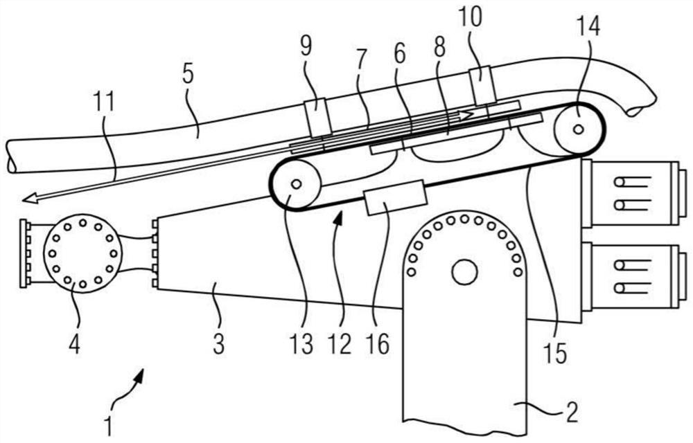
Fig. 1 shows a detail of a medical examination and/or treatment device 1, which has a robot 2, which is only partially shown, on which an arm 3 that can be moved in multiple axes is mounted. The pivotally movable arm 3 supports a C-arm 4 on its free end, which is a component of an angiographic apparatus. Fig. 1 shows a medical examination and/or treatment device 1 having a cable 5, a section of which is shown. The cable 5 is connected to the C-arm 4 on the one hand and to the robot 2 on the other hand. During the movement of the multiaxially movable C-arm 4, the cable 5 must follow accordingly without significant tensile stresses occurring therein. A cable harness is contained in the cable 5, which includes data lines, control lines and power supply lines for supplying the C-arm 4 with power.
A telescopic retractor 6 is used as a means for following the cable 5 when the C-arm is moved, the telescopic retractor 6 being arranged on the robot 2, more precisely on the arm 3 of the robot 2.
In the embodiment shown, the telescopic retractor 6 has two telescopic elements 7, 8. The telescopic element 7 is fixedly connected to the cable 5 by means of holding elements 9, 10. The telescopic part 8 is arranged in a stationary manner on the arm 3. However, alternative embodiments are also conceivable in which the telescopic part 8 is arranged so as to be slidable relative to the arm 3.
The telescopic retractor 6 has a drive (not shown) by means of which the telescopic part 7 can slide relative to the telescopic part 8, the direction of movement of the telescopic part 7 being indicated by the double arrow 11.
The component of the telescopic tractor 6 is furthermore a belt drive 12, which comprises two deflection rollers 13, 14, which are mounted at a distance from one another and rotatably on the arm 3 and are coupled to one another by a belt 15. A continuous belt 15 surrounds the two deflecting rollers 13, 14, the upper run of the belt 15 being fixedly connected to the telescopic element 7. The lower run of the belt 15 has a balancing mass 16, so that when the telescopic part 7 moves in one direction, the balancing mass 16 moves in the opposite direction. The balancing mass 16 achieves mass balancing, which gives rise to the advantage that the operating force for moving the telescopic element 7 does not need to be high.
When the C-arm 4 is moved, the cable 5 is followed correspondingly by the movement of the telescopic retractor 6, so that the cable 5 can follow the various movements of the C-arm 4.
Fig. 2 shows a detail of a further exemplary embodiment of a medical examination and/or treatment device 1 with a telescopic retractor 21. In contrast to the previous exemplary embodiment, the arm 3 of the robot has a total of three movable telescopic parts 17,18,19, wherein the telescopic part 17, which is shown in the lowermost position in fig. 2, is movable relative to a stationary guide part 20. The telescopic member 19 is connected to the cable 5 via the holding members 9,10 as in the previous embodiment. In contrast to the previous exemplary embodiment, the telescopic retractor 21 shown in fig. 2 has the advantage that the same retraction path can be achieved even with a smaller length of the individual telescopic elements 17,18, 19.
Fig. 3 shows the telescopic elements 17,18,19 of a telescopic retractor 21, wherein the telescopic element 18 has deflection rollers 13, 14 which are kinematically coupled to one another by means of a cable 22. In fig. 3, telescoping part 18 is shown coupled with telescoping part 19 via its upper return section and telescoping part 17 via its lower return section. By means of this kinematic coupling, the telescopic parts 17, 19 are controlled in such a way that they move synchronously relative to one another.
Fig. 4 shows a further embodiment of a telescopic retractor 23 with a first belt drive 24, a second belt drive 25 and a third belt drive 26. Figure 5 shows an additional perspective view of the telescopic retractor 23 shown in figure 4. The holders 9,10 for the cables 5 are connected to parts of the first belt drive 24. The first belt drive 24 is connected to a second belt drive 25, which second belt drive 25 is in turn connected to a third belt drive 26. Such a triple telescopic retractor 23 is driven electrically, whereby the forces in the cable 5 are reduced as much as possible. The telescopic tractor 23 can be controlled in such a way that only a single belt drive is driven, whereby the movement of the cable 5 is converted in a ratio of 1:3, whereby the distance is increased by a factor of three. Wherein one of the belt drives is either driven linearly, alternatively the telescopic tractor 23 is driven by one of the shown (drive equipped) diverting rollers. Since the individual telescopic elements are coupled kinematically to one another by means of a belt drive, it is not important in which position the drive takes place, since all components of the telescopic retractor 23 are forcibly displaced.
Fig. 6 shows a detail of the telescopic retractor 23 shown in fig. 4 and 5, wherein a balancing mass 28 is arranged on the telescopic part 27. The balancing mass 28 can be moved by means of a telescopic element for causing the required mass compensation or reduction of the return force.
Fig. 7 to 12 show a further exemplary embodiment of a medical examination and/or treatment device 29, which, like the previous exemplary embodiments, has a robot 30 with a multiaxially movable arm 31, on which arm 31 a C-arm 4 is mounted, which is movable about multiple axes. The hinge 33 with the two hinge sections 34, 35 serves as a means for following the cable 32. The hinge 33 is arranged on the arm 31 of the robot 30, connected to the arm 31 by means of a hinge section 34 and the hinge 35 is connected to the cable 32. The cable 32 can follow correspondingly by means of the hinge 33 when the arm 31 of the robot 30 is moved and/or the C-arm 4 is moved relative to the arm 31, so that the required length of the cable 32 can be provided at various positions. Fig. 7 and 8 show the hinge 33 in the final position, in which the two hinge sections 34, 35 are oriented approximately parallel. In this position, the end of the hinge section 35 facing the C-arm 4 is particularly close to the C-arm. Fig. 9 shows a further perspective view of the medical examination and/or treatment device 29.
Fig. 10 shows the device 29 in a position in which the hinge 33 is retracted, i.e. the two hinge sections 34, 35 enclose an acute angle. Accordingly, the cable 32 is in the pulled-back position with respect to the preceding figures, as can be seen from the formed loop 36. The movement or adjustment of the joint 33 is effected by means of a drive motor, which is arranged at the connection point between the two joint sections 34, 35.
Fig. 11 and 12 show the hinge 33 in an intermediate position between the fully stowed position shown in fig. 10 and the fully deployed position shown in fig. 7 to 9. Fig. 11 shows a detail view of fig. 12 from the opposite side.
In fig. 11 and 12, the cable 32 is shown to be moved along a fixed path by corresponding control of the driven hinge 33. Depending on the position of the hinge 33, the cable 32 moves towards or away from the C-arm. The cable 32 with the sleeve can be easily cleaned, so that it meets the hygienic requirements in the medical field.
Although the invention has been described and illustrated in detail in connection with preferred embodiments thereof, the invention is not limited to the disclosed embodiments and other variations may be derived therefrom by those skilled in the art without departing from the scope of the invention.
List of reference numerals
1 examination and/or treatment device
2 robot
3 arm
4C-shaped arm
5 Cable
6 telescopic tractor
7 expansion piece
8 expansion piece
9 holding member
10 holder
11 double arrow
12 belt transmission
13 steering roller
14 steering roller
15 leather belt
16 balance mass
17 telescoping piece
18 telescoping member
19 telescoping piece
20 guide member
21 telescopic tractor
22 rope
23 extension tractor
24 belt transmission
25 belt transmission
26 belt transmission
27 expansion piece
28 balance mass
29 examination and/or treatment device
30 robot
31 arm
32 electric cable
33 hinge
34 hinge section
35 hinge section
36 bending ring
- 上一篇:一种医用注射器针头装配设备
- 下一篇:一种排粪造影检查用的免冲水马桶