Clamp for fixing annular workpiece
阅读说明:本技术 一种用于固定环形工件的夹具 (Clamp for fixing annular workpiece ) 是由 史书林 于 2021-09-27 设计创作,主要内容包括:本发明涉及机械夹具技术领域,公开了一种用于固定环形工件的夹具,包括:机架、驱动螺杆、第一连杆、连杆机构和活动压块,驱动螺杆沿水平方向转动连接于机架内,驱动螺杆的一端延伸出机架的侧壁,驱动螺杆上具有两段螺向相反的螺纹,每段螺纹上各螺接有一驱动螺母,第一连杆第一端与驱动螺母铰接,连杆机构呈平行四边形结构,连杆机构的相邻连杆之间均铰接,连杆机构的下部位于机架内,连杆机构的上部沿机架上端面的滑槽延伸出机架,连杆机构的下端连接于机架上,连杆机构的下端与第一连杆的第二端铰接,活动压块铰接于连杆机构的上端,本发明提供的夹具,可以满足结构简单紧凑、自适应不同表面的工件、具有自锁功能、操作方便的工作要求。(The invention relates to the technical field of mechanical clamps, and discloses a clamp for fixing an annular workpiece, which comprises: the clamp comprises a frame, a driving screw rod, a first connecting rod, a connecting rod mechanism and a movable pressing block, wherein the driving screw rod is rotatably connected into the frame along the horizontal direction, one end of the driving screw rod extends out of the side wall of the frame, two sections of threads with opposite screw directions are arranged on the driving screw rod, each section of thread is respectively screwed with a driving nut, the first end of the first connecting rod is hinged with the driving nut, the connecting rod mechanism is in a parallelogram structure, adjacent connecting rods of the connecting rod mechanism are hinged, the lower part of the connecting rod mechanism is positioned in the frame, the upper part of the connecting rod mechanism extends out of the frame along a chute on the upper end surface of the frame, the lower end of the connecting rod mechanism is connected onto the frame, the lower end of the connecting rod mechanism is hinged with the second end of the first connecting rod, and the movable pressing block is hinged onto the upper end of the connecting rod mechanism, the self-locking device can meet the working requirements of simple and compact structure, self-adaption to workpieces with different surfaces, self-locking function and convenient operation.)
1. A fixture for fixing an annular workpiece, comprising a frame (7), characterized by further comprising:
the driving screw (12) is rotatably connected into the rack (7) along the horizontal direction, one end of the driving screw (12) extends out of the side wall of the rack (7), two sections of threads with opposite screw directions are arranged on the driving screw (12), and each section of threads is respectively screwed with a driving nut (8);
a first connecting rod (14) with a first end hinged with the driving nut (8);
the connecting rod mechanisms are of parallelogram structures, adjacent connecting rods of the connecting rod mechanisms are hinged, the lower parts of the connecting rod mechanisms are positioned in the rack (7), the upper parts of the connecting rod mechanisms extend out of the rack (7) along a sliding groove (13) on the upper end surface of the rack (7), the lower ends of the connecting rod mechanisms are connected to the rack (7), and the lower ends of the connecting rod mechanisms are hinged with the second end of the first connecting rod (14);
the movable pressing block (1) is hinged to the upper end of the connecting rod mechanism, and the movable pressing block (1) is located on one side, close to the rack (7), of the connecting rod mechanism.
2. A clamp for securing an annular workpiece according to claim 1 in which each set of linkage mechanisms comprises:
the bracket (15) is fixed on one side of the rack (1) close to the first connecting rod (14);
the first end of the lever (4) is hinged with the second end of the first connecting rod (14), the second end of the lever extends out of the upper end face of the rack (7), and the lower part of the lever (4) is hinged with the bracket (15);
the second connecting rod (5) is arranged in parallel with the lever (4), the second connecting rod (5) is located on the inner side of the lever (4), the first end of the second connecting rod (5) is hinged to the support (15), the first end of the second connecting rod (5) extends out of the upper end face of the rack (7), and the second connecting rod (5) is flush with the upper end of the lever (4);
the third connecting rod (3) is parallel to the upper end face of the rack (7), the third connecting rod (3) is located above the rack (7), the second ends of the lever (4) and the second connecting rod (5) are hinged to the third connecting rod (3) respectively, and the movable pressing blocks (1) are hinged to the bottoms of the sides, away from each other, of the two third connecting rods (3) respectively.
3. A clamp for fixing annular workpieces according to claim 2, characterized in that said support (15) comprises:
the upper end of the vertical rod (150) is fixed with the inner wall of the upper side of the rack (7);
the cross rod (151) is perpendicular to the vertical rod (150), the first end of the cross rod (151) is fixed to the lower end of the vertical rod (150), the second end of the cross rod (151) is hinged to the first end of the second connecting rod (5), and the lower portion of the lever (4) is hinged between the first end and the second end of the cross rod (151).
4. The clamp for fixing the annular workpiece according to claim 2, wherein an adjusting bolt (2) is screwed on the third connecting rod (3), and the movable pressing block (1) is hinged at the lower end of the adjusting bolt (2).
5. The clamp for fixing annular workpieces according to claim 4, characterized in that the movable pressure piece (1) is articulated to the lower end of the adjusting screw (2) by means of a ball joint (11).
6. A clamp for fixing annular workpieces according to claim 1, characterized in that a hand wheel (9) is fixed to the end of the drive screw (12) which extends out of the machine frame (7).
7. A clamp for fixing annular workpieces according to claim 6, characterized in that the side of the drive screw (12) which extends beyond the machine frame (7) is connected to the machine frame (7) by means of a screw end cap (10), the screw end cap (10) being fixed to the machine frame (7).
8. A clamp for fixing annular workpieces according to claim 1, characterized in that the drive nut (8) is articulated to the first end of the first connecting rod (14) by means of an articulation seat.
Technical Field
The invention relates to the technical field of mechanical clamps, in particular to a clamp for fixing an annular workpiece.
Background
The jig is a device for fixing a processing object to occupy a correct position for receiving construction or inspection in a machine manufacturing process, and is also called a jig. In a broad sense, any device used to quickly, conveniently and safely mount a workpiece at any stage in a process may be referred to as a jig.
The clamp for fixing the annular workpiece on the market at present has the defects that the clamping angle can be changed along with the change of the size of the workpiece, the clamping force is uneven, the mechanism is complex, a locking mechanism is not arranged, the space is limited, and the overall comprehensive performance is poor.
Therefore, a clamp which has a simple and compact structure, is adaptive to workpieces with different sizes and surfaces, has a self-locking function and is convenient to operate is urgently needed.
Disclosure of Invention
The invention provides a clamp for fixing an annular workpiece, which can meet the working requirements of simple and compact structure, self-adaptive surface workpiece, self-locking function and convenient operation.
The invention provides a clamp for fixing an annular workpiece, which comprises:
a frame;
the driving screw is rotatably connected into the rack in the horizontal direction, one end of the driving screw extends out of the side wall of the rack, two sections of threads with opposite screw directions are arranged on the driving screw, and each section of threads is respectively screwed with a driving nut;
the first end of the first connecting rod is hinged with the driving nut;
the connecting rod mechanisms are of parallelogram structures, adjacent connecting rods of the connecting rod mechanisms are hinged, the lower parts of the connecting rod mechanisms are positioned in the rack, the upper parts of the connecting rod mechanisms extend out of the rack along a sliding groove on the upper end surface of the rack, the lower ends of the connecting rod mechanisms are connected to the rack, and the lower ends of the connecting rod mechanisms are hinged with the second end of the first connecting rod;
the movable pressing block is hinged to the upper end of the connecting rod mechanism and is positioned on one side, close to the rack, of the connecting rod mechanism.
Optionally, each set of linkage mechanisms comprises:
the bracket is fixed on one side of the rack close to the first connecting rod;
the first end of the lever is hinged with the second end of the first connecting rod, the second end of the lever extends out of the upper end face of the rack, and the lower part of the lever is hinged with the bracket;
the second connecting rod is arranged in parallel with the lever, is positioned on the inner side of the lever, is hinged with the bracket at a first end and extends out of the upper end surface of the rack, and is flush with the upper end of the lever;
and the third connecting rod is arranged in parallel to the upper end face of the rack and is positioned above the rack, the second ends of the lever and the second connecting rod are respectively hinged with the third connecting rod, and the movable pressing blocks are respectively hinged at the bottom of one side, away from each other, of the two third connecting rods.
Optionally, the bracket comprises:
the upper end of the vertical rod is fixed with the inner wall of the upper side of the rack;
the cross rod is perpendicular to the vertical rod, the first end of the cross rod is fixed to the lower end of the vertical rod, the second end of the cross rod is hinged to the first end of the second connecting rod, and the lower portion of the lever is hinged between the first end and the second end of the cross rod.
Optionally, the third connecting rod is screwed with an adjusting bolt, and the movable pressing block is hinged to the lower end of the adjusting bolt.
Optionally, the movable pressing block is hinged to the lower end of the adjusting bolt through a ball joint.
Optionally, a hand wheel is fixed at one end of the driving screw rod extending out of the frame.
Optionally, one side of the driving screw extending out of the rack is connected with the rack through a screw end cover, and the screw end cover is fixed with the rack.
Optionally, the drive nut is hinged to the first end of the first link via a hinge mount.
Compared with the prior art, the invention has the beneficial effects that: the clamp for fixing the annular workpiece provided by the invention has the advantages that the two sections of threads on the driving screw are opposite in rotation direction, and the driving nuts are restricted by the first connecting rod and cannot rotate, so that the screw pushes the two driving nuts to move towards or away from each other, when the two driving nuts move towards each other, the two driving nuts respectively push the connecting rod mechanism through the first connecting rod hinged with the two driving nuts to move, the connecting rod mechanism drives the movable pressing block to press the annular workpiece tightly, on the contrary, when the two driving nuts move towards each other, the movable pressing block loosens the workpiece and moves towards the axis of the annular workpiece to enable the discharging space to be formed so as to remove the workpiece, because the movable pressing block can rotate around the connecting rod mechanism, even if the plane inclination angle of the surface of the workpiece changes, the movable pressing block can be fully contacted with the surface of the workpiece, and because the driving nuts cannot rotate, the screw cannot be driven to rotate, therefore, the clamp has the locking function, has a simple and compact structure, can conveniently clamp, loosen and unload the annular workpiece, has the thread locking function, and is self-adaptive to the change of the size and the surface inclination angle of the workpiece.
Drawings
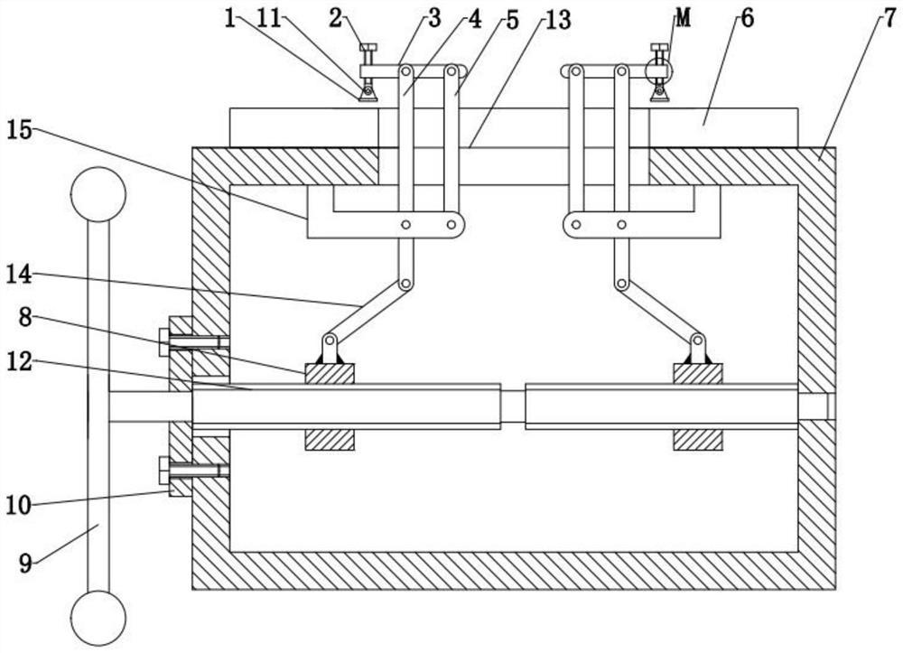
FIG. 1 is a schematic structural diagram of a fixture for fixing an annular workpiece according to an embodiment of the present invention;
FIG. 2 is a schematic structural diagram of a bracket according to an embodiment of the present invention;
fig. 3 is a partially enlarged schematic view of a portion M in fig. 1.
Description of reference numerals:
1-movable pressing block, 2-adjusting bolt, 3-third connecting rod, 4-lever, 5-second connecting rod, 6-workpiece, 7-frame, 8-driving nut, 9-hand wheel, 10-screw end cover, 11-ball joint, 12-driving screw, 13-sliding groove, 14-first connecting rod, 15-bracket, 150-vertical rod and 151-cross rod.
Detailed Description
An embodiment of the present invention will be described in detail below with reference to the accompanying drawings, but it should be understood that the scope of the present invention is not limited to the embodiment.
In the description of the present invention, it is to be understood that the terms "center", "longitudinal", "lateral", "length", "width", "thickness", "upper", "lower", "front", "rear", "left", "right", "vertical", "horizontal", "top", "bottom", "inner", "outer", "axial", "radial", "circumferential", etc. indicate orientations or positional relationships based on those shown in the drawings, and are only for convenience of describing technical solutions of the present invention and simplifying the description, but do not indicate or imply that the device or element referred to must have a specific orientation, be constructed and operated in a specific orientation, and thus, should not be construed as limiting the present invention.
As shown in fig. 1, an embodiment of the present invention provides a fixture for fixing an annular workpiece, including: the device comprises a rack 7, a driving screw 12, a first connecting rod 14, a connecting rod mechanism and a movable pressing block 1, wherein the driving screw 12 is rotatably connected in the rack 7 along the horizontal direction, one end of the driving screw 12 extends out of the side wall of the rack 7, two sections of threads with opposite screw directions are arranged on the driving screw 12, a driving nut 8 is respectively screwed on each section of threads, the first end of the first connecting rod 14 is hinged with the driving nut 8, the connecting rod mechanism is of a parallelogram structure, the adjacent connecting rods of the connecting rod mechanism are hinged, the lower part of the connecting rod mechanism is positioned in the rack 7, the upper part of the connecting rod mechanism extends out of the rack 7 along a sliding chute 13 on the upper end surface of the rack 7, the lower end of the connecting rod mechanism is connected to the rack 7, the lower end of the connecting rod mechanism is hinged with the second end of the first connecting rod 14, the movable pressing block 1 is hinged to the upper end of the connecting rod mechanism, and the movable pressing block 1 is positioned on one side of the connecting rod mechanism close to the rack 7.
The clamp for fixing the annular workpiece provided by the invention has the advantages that the two sections of threads on the driving screw are opposite in rotation direction, and the driving nuts are restricted by the first connecting rod and cannot rotate, so that the screw pushes the two driving nuts to move towards or away from each other, when the two driving nuts move towards each other, the two driving nuts respectively push the connecting rod mechanism through the first connecting rod hinged with the two driving nuts to move, the connecting rod mechanism drives the movable pressing block to press the annular workpiece tightly, on the contrary, when the two driving nuts move towards each other, the movable pressing block loosens the workpiece and moves towards the axis of the annular workpiece to enable the discharging space to be formed so as to remove the workpiece, because the movable pressing block can rotate around the connecting rod mechanism, even if the plane inclination angle of the surface of the workpiece changes, the movable pressing block can be fully contacted with the surface of the workpiece, and because the driving nuts cannot rotate, the screw cannot be driven to rotate, therefore, the clamp has the locking function, has a simple and compact structure, can conveniently clamp, loosen and unload the annular workpiece, has the thread locking function, and is self-adaptive to the change of the size and the surface inclination angle of the workpiece.
In the present embodiment, each set of link mechanisms includes: the support 15 is fixed on one side, close to the first connecting rod 14, of the rack 1, the first end of the lever 4 is hinged to the second end of the first connecting rod 14, the second end extends out of the upper end face of the rack 7, the lower portion of the lever 4 is hinged to the support 15, the second connecting rod 5 is arranged in parallel to the lever 4, the second connecting rod 5 is located on the inner side of the lever 4, the first end of the second connecting rod 5 is hinged to the support 15, the first end of the second connecting rod 5 extends out of the upper end face of the rack 7, the second connecting rod 5 is flush with the upper end of the lever 4, the third connecting rod 3 is arranged in parallel to the upper end face of the rack 7, the third connecting rod 3 is located above the rack 7, the second ends of the lever 4 and the second connecting rod 5 are hinged to the third connecting rods 3 respectively, and the movable pressing block 1 is hinged to the bottom of one side, far away from each other, of the two third connecting rods 3.
In the present embodiment, the left thread of the driving screw 12 is right-handed, the right thread is left-handed, the driving screw 12 is rotated to rotate clockwise, since the thread turning direction of the left half of the driving screw 12 is right-handed, and the left driving nut 8 is constrained by the left first connecting rod 14 and cannot rotate, the driving screw 12 pushes the left driving nut 8 to move linearly to the left, and since the thread turning direction of the right half of the driving screw 12 is left-handed, and the right driving nut 8 is constrained by the right first connecting rod 14 and cannot rotate, the driving screw 12 pushes the right driving nut 8 to move linearly to the right; the two driving nuts 8 respectively push the lever 4 to rotate through the first connecting rod 14 hinged with the two driving nuts, the rotation directions of the two levers 4 are opposite, the lever 4 pushes the lever 4, the second connecting rod 5, the third connecting rod 3 and the support 15 to form a pair of parallelogram connecting rod mechanisms to move, the parallelogram connecting rod mechanisms drive the movable pressing block 1 to press the annular workpiece 6, on the contrary, when the driving screw 12 rotates anticlockwise, the movable pressing block 1 loosens the workpiece 6 and moves towards the axis of the annular workpiece to allow a discharging space to be formed, so that the workpiece can be removed.
Referring to fig. 2, the bracket 15 includes: montant 150 and horizontal pole 151, the upper end of montant 150 is fixed with the upside inner wall of frame 7, and horizontal pole 151 perpendicular to montant 150 sets up, and the first end of horizontal pole 151 is fixed with montant 150's lower extreme, and the second end of horizontal pole 151 is articulated with the first end of second connecting rod 5, and the lower part of lever 4 articulates between the first end and the second end of horizontal pole 151.
The bracket 15 is provided in an L-shape, so that its influence on the lever 4 and the second link 5 can be avoided.
Referring to fig. 3, an adjusting bolt 2 is screwed on the third connecting rod 3, the movable pressing block 1 is hinged to the lower end of the adjusting bolt 2, and the distance between the movable pressing block 1 and the workpiece 6 can be changed by adjusting the adjusting bolt 2 on the movable pressing block 1, so that the workpieces can be clamped in different sizes.
Optionally, the movable pressing block 1 is hinged to the lower end of the adjusting bolt 2 through the ball joint 11, and the movable pressing block 1 can rotate around the ball joint 11, so that the movable pressing block 1 can be fully contacted with the surface of the workpiece 6 even if the plane inclination angle of the surface of the workpiece changes.
Optionally, a hand wheel 9 is fixed at one end of the driving screw 12 extending out of the frame 7, and it is more convenient to operate the driving screw 12 through the hand wheel 9.
Optionally, one side of the driving screw 12 extending out of the frame 7 is connected to the frame 7 through a screw end cover 10, and the screw end cover 10 is fixed to the frame 7.
Alternatively, the drive nut 8 is hinged to the first end of the first link 14 by means of a hinge seat.
The above disclosure is only for a few specific embodiments of the present invention, however, the present invention is not limited to the above embodiments, and any variations that can be made by those skilled in the art are intended to fall within the scope of the present invention.
- 上一篇:一种医用注射器针头装配设备
- 下一篇:一种航空发动机包容环与机匣用定位装置及粘接方法