Cow dung processing apparatus
阅读说明:本技术 一种牛粪处理装置 (Cow dung processing apparatus ) 是由 童超 王学兵 张玥 孙爽 邓立新 王新庄 张元� 郑佳 周玄 凌泽威 王艺臻 于 2021-07-02 设计创作,主要内容包括:本发明涉及一种牛粪处理装置,包括清扫机构、预脱水机构、污水处理机构和精脱水机构,所述清扫机构通过下水管道与预脱水机构连通,预脱水机构与所述污水处理机构之间设有沼气机构并通过管道连通,预脱水机构与所述精脱水机构通过物料输送机构连通,精脱水机构出料口处设有制料机构,本发明通过清扫机构将牛粪快速的进行收集并对饲养场地进行清扫,通过预脱水机构对牛粪进行初步脱水,粪水进入沼气发酵然后进入污水处理机构进行最后处理,减少环境污染,牛粪经过精脱水机构进行脱水并通过制料机构压制成块便于储存和制肥。(The invention relates to a cow dung treatment device, which comprises a cleaning mechanism, a pre-dewatering mechanism, a sewage treatment mechanism and a fine dewatering mechanism, wherein the cleaning mechanism is communicated with the pre-dewatering mechanism through a sewer pipeline, a methane mechanism is arranged between the pre-dewatering mechanism and the sewage treatment mechanism and is communicated with the sewage treatment mechanism through a pipeline, the pre-dewatering mechanism is communicated with the fine dewatering mechanism through a material conveying mechanism, and a material preparation mechanism is arranged at a discharge port of the fine dewatering mechanism.)
1. The utility model provides a cow dung processing apparatus, includes cleans mechanism (1), dewaters mechanism (5), sewage treatment mechanism (19) and smart dewatering mechanism in advance, its characterized in that: the cleaning mechanism (1) is communicated with the pre-dewatering mechanism (5) through a sewer pipe, a methane mechanism (28) is arranged between the pre-dewatering mechanism (5) and the sewage treatment mechanism (19) and is communicated through a pipe, the pre-dewatering mechanism (5) is communicated with the fine dewatering mechanism through a material conveying mechanism, and a material making mechanism (62) is arranged at the discharge outlet of the fine dewatering mechanism.
2. A cow dung processing device according to claim 1, characterized in that: cleaning mechanism (1) including being cable wire fixer (2) that the rectangle was arranged, being equipped with the cable wire on cable wire fixer (2), being equipped with on the cable wire rather than fixed connection's clear excrement mechanism (3), still being equipped with motor (4) on the cable wire, clear excrement mechanism (3) include cowl (301), cowl (301) both sides are equipped with curb plate (302), are equipped with on cowl (301) and wash mechanism (305) rather than fixed connection, are equipped with in washing mechanism (305) and wash motor (306), wash mechanism (305) be equipped with wash brush (303) that motor (306) are connected, be equipped with universal wheel (304) on washing mechanism (3), still be equipped with water tank and nozzle in washing mechanism (305).
3. A cow dung processing device according to claim 2, characterized in that: the pre-dehydration mechanism (5) comprises a support frame (11), a dehydration barrel (6) is arranged on the support frame (11), a cow dung feeding hole (7) is formed in the dehydration barrel (6), and a dung water outlet (13) is formed in the dehydration barrel (6); be equipped with dehydration squeeze roll (8) in dehydration bucket (6), be equipped with first helical blade (9) on dehydration squeeze roll (8), dehydration bucket (6) one end is equipped with cow dung discharge gate (10), and the pitch of first helical blade (9) reduces from cow dung feed inlet (7) to cow dung discharge gate (10) direction gradually, be equipped with on support frame (11) with dehydration motor (12) of dehydration squeeze roll (8) hub connection.
4. A cow dung processing device according to claim 3, characterized in that: the biogas mechanism (28) comprises a biogas tank, a protective shell (29) is arranged on the outer side of the biogas tank along the circumference, a biogas stirring motor (31) is arranged on the biogas tank, a liquid dung inlet (32) and an exhaust port (33) are arranged on the biogas tank, a liquid dung pump (30) communicated with the liquid dung inlet (32) is arranged on the biogas tank, and a water inlet of the liquid dung pump (30) is communicated with the liquid dung water outlet (13); the stirring mechanism (34) connected with the shaft of the methane stirring motor (31) is arranged in the methane tank (28), the stirring mechanism (34) comprises a stirring shaft, the stirring shaft is sequentially provided with a first stirring mechanism (341), a second stirring mechanism (342), a third stirring mechanism (343) and a fourth stirring mechanism (344) from bottom to top, and three propelling blades are arranged on the fourth stirring mechanism (344).
5. A cow dung processing device according to claim 4, characterized in that: the third stirring mechanism (343) comprises a driving tooth (3421) fixedly connected with the stirring shaft, a driven tooth (3422) meshed with the driving tooth (3421) is arranged on the driving tooth (3421), a stirring wheel (3424) meshed with the driven tooth (3422) is arranged on the driven tooth (3422), four propelling blades are arranged on the stirring wheel (3424), the third stirring mechanism (343) further comprises a fixing clamp which is connected with the driven stirring shaft and is matched with the driven tooth (3422) and the stirring wheel (3424), the second stirring mechanism (342) comprises a driving tooth (3421) fixedly connected with the stirring shaft, a driven tooth (3422) meshed with the driving tooth (3421) is arranged on the driving tooth (3421), a speed change wheel (3423) meshed with the driven tooth (3422) is arranged on the driven tooth (3423), a stirring wheel (3424) meshed with the speed change wheel (3423) is arranged on the speed change wheel (3423), six propelling blades are arranged on the stirring wheel (3424), and the second stirring mechanism (342) further comprises a stirring shaft which is connected with the driven shaft and is matched with the driven tooth (3422) and the fixing clamp which is matched with the stirring wheel (3424); the lower end of the methane tank is provided with a slag liquid outlet (35), and the slag liquid outlet (35) is provided with a slag discharge pump (36) communicated with the slag liquid outlet.
6. A cow dung processing device according to claim 5, characterized in that: the sewage treatment mechanism (19) comprises an aeration tank (20), an MBR membrane tank (22), a control device (26) and a reclaimed water tank (27), wherein a liquid inlet pipe communicated with the deslagging pump (36) is arranged on the aeration tank (20), a water feeding pump (15) communicated with the reclaimed water tank (27) is arranged on the liquid inlet pipe, a water feeding box (16) communicated with the aeration tank (20) is arranged on the aeration tank (20), a sewage stirring motor (17) is arranged on the aeration tank (20), and an air blower (21) is arranged on the aeration tank (20); a stirring mechanism (18) connected with the sewage stirring motor (17) is arranged in the aeration tank (20), the stirring mechanism (18) comprises a first gear (183), at least one stirrer (181) is meshed on the first gear (183), a second gear (182) is meshed on the stirrer (181), and at least one stirrer (181) is meshed on the second gear (182); a circulating pump (14) is arranged in the aeration tank (20), an aeration pipe (23) communicated with the circulating pump (14) and the air blower (21) is arranged in the aeration tank (20), and the aeration pipe (23) comprises an air pipe communicated with the air blower (21) and a water pipe communicated with the circulating pump (14).
7. A cow dung processing device according to claim 6, characterized in that: MBR membrane jar (22) with be equipped with the raceway between aeration tank (20), be equipped with the valve on the raceway, be equipped with MBR module (24) in MBR membrane jar (22), MBR module (24) lower extreme be equipped with MBR membrane aeration pipe of air-blower (21) intercommunication is equipped with in MBR membrane jar (22) with sludge pump (25) of aeration tank (20) intercommunication.
8. A cow dung processing device according to claim 7, characterized in that: the fine dewatering mechanism comprises a freezing mechanism (37) and a dewatering mechanism (51), the freezing mechanism (37) comprises a refrigeration tank, a dewatered cow dung feeding hole (46) communicated with the cow dung discharging hole (10) is formed in the refrigeration tank, a frozen cow dung outlet (42) is formed in the refrigeration tank, a first motor (39) and a second motor (43) are arranged at two ends of the refrigeration tank, an air circulating pump (45) is arranged on the refrigeration tank, an air inlet of the air circulating pump (45) is communicated with one end of the refrigeration tank, and an air outlet of the air circulating pump (45) is communicated with the other end of the refrigeration tank; be equipped with in the refrigeration jar with conveying roller (40) of first motor (39) hub connection is equipped with the transport paddle leaf on conveying roller (40), be equipped with in the refrigeration jar with agitator (41) of second motor (43) hub connection, agitator (41) internal face be equipped with conveying roller (40) matched with stirring rod (411), be equipped with insulating layer (47) on the refrigeration jar internal surface, be equipped with cooling tube layer (471) on insulating layer (47), be equipped with on the refrigeration jar with cooling tube layer (471) the coolant liquid of intercommunication enter (44) and coolant liquid export (38).
9. A cow dung processing device according to claim 8, characterized in that: the dehydration mechanism (51) comprises a dehydration tank, a dehydration stirring motor (48) is arranged on the dehydration tank, a stirring conveying roller (57) connected with the dehydration stirring motor (48) through a shaft is arranged in the dehydration tank, blades are arranged on the stirring conveying roller (57), a heating pipe layer (55) is arranged in the stirring conveying roller (57), and a second heating agent inlet (58) and a second heating agent outlet (59) which are communicated with the heating pipe layer (55) are arranged on the dehydration tank; be equipped with on the drain sump with vacuum pump (52) rather than the intercommunication, be equipped with on the drain sump with dehydration feed inlet (50) of freezing cow dung export (42) intercommunication, dehydration feed inlet (50) department is equipped with valve (49), is equipped with dry excrement discharge gate (61) on the drain sump, is equipped with heat preservation (54) in the drain sump, is equipped with heating tube layer (55) on heat preservation (54), be equipped with on the drain sump with first heating agent import (53) and first heating agent export (60) of heating tube layer (55) intercommunication are equipped with heat dissipation layer (56) on heating tube layer (55), material preparation mechanism (62) with dry excrement discharge gate (61) intercommunication.
Technical Field
The invention belongs to the technical field of mechanical equipment, and particularly relates to a cow dung treatment device.
Background
Because pollutants such as livestock excrement and urine and rural rubbish often contain a large amount of moisture, therefore, utilize the refuse transport vechicle, the rubbish compression car, can carry out dewatering drying process to the pollutant before machines such as rubbish recovery car are retrieved, in order to reduce the processing degree of difficulty, traditional treatment only is simple to excrement and urine dehydration treatment, use a large amount of water to cause the waste of water resource in the cow dung collection process, sewage is not through handling, pollute the water body, cow dung after the dehydration still contains great water content simultaneously and often needs insolateing to carry out resource utilization again, the cycle length, it gives off gas has great pollution to the surrounding environment.
Disclosure of Invention
The invention aims to solve the problems in the background technology, and provides a cattle manure processing device which can rapidly collect cattle manure through a cleaning mechanism and clean a feeding field, preliminarily dehydrates the cattle manure through a pre-dehydration mechanism, ferments the manure water through methane and finally processes the manure water through a sewage processing mechanism, reduces the environmental pollution, dehydrates the cattle manure through a fine dehydration mechanism, and presses the manure into blocks through a material preparing mechanism, so that the cattle manure is convenient to store and fertilizer.
In order to achieve the purpose, the technical scheme adopted by the invention is as follows: the utility model provides a cow dung processing apparatus, is including cleaning the mechanism, dehydrating mechanism, sewage treatment mechanism and smart dehydration mechanism in advance, clean the mechanism through sewer line and dehydration mechanism intercommunication in advance, dehydration mechanism in advance with be equipped with marsh gas mechanism between the sewage treatment mechanism and through the pipeline intercommunication, dehydration mechanism in advance with smart dehydration mechanism passes through material conveying mechanism intercommunication, and smart dehydration mechanism discharge gate department is equipped with system material mechanism.
Preferably, the cleaning mechanism comprises a steel cable fixer which is arranged in a rectangular shape, the steel cable fixer is provided with a steel cable, the steel cable is provided with a feces cleaning mechanism which is fixedly connected with the steel cable, the steel cable is further provided with a motor, the feces cleaning mechanism comprises an arc baffle, side plates are arranged on two sides of the arc baffle, the arc baffle is provided with a washing mechanism which is fixedly connected with the arc baffle, a washing motor is arranged in the washing mechanism, the washing mechanism is provided with a washing brush which is connected with the washing brush motor, the washing mechanism is provided with a universal wheel, and the washing mechanism is further provided with a water tank and a nozzle.
Preferably, the pre-dewatering mechanism comprises a support frame, a dewatering barrel is arranged on the support frame, a cow dung feeding hole is formed in the dewatering barrel, and a dung water outlet is formed in the dewatering barrel; be equipped with the dehydration squeeze roll in the dehydration bucket, be equipped with first helical blade on the dehydration squeeze roll, dehydration bucket one end is equipped with the cow dung discharge gate, and first helical blade's pitch reduces from cow dung feed inlet to cow dung discharge gate direction gradually, be equipped with on the support frame with the dehydration motor of dehydration squeeze roll hub connection.
Preferably, the biogas mechanism comprises a biogas tank, a protective shell is arranged on the outer side of the biogas tank along the circumference, a biogas stirring motor is arranged on the biogas tank, a liquid manure inlet and an exhaust port are arranged on the biogas tank, a liquid manure pump communicated with the liquid manure inlet is arranged on the biogas tank, and a water inlet of the liquid manure pump is communicated with a liquid manure outlet; the stirring mechanism is connected with the methane stirring motor shaft and comprises a stirring shaft, the stirring shaft is sequentially provided with a first stirring mechanism, a second stirring mechanism, a third stirring mechanism and a fourth stirring mechanism from bottom to top, and the fourth stirring mechanism is provided with three propelling blades.
Preferably, the third stirring mechanism comprises a driving tooth fixedly connected with the stirring shaft, the driving tooth is provided with a driven tooth engaged with the driving tooth, the driven tooth is provided with a stirring wheel engaged with the driven tooth, the stirring wheel is provided with four propelling paddles, the third stirring mechanism further comprises a fixing clamp connected with the driven stirring shaft and matched with the driven tooth and the stirring wheel, the second stirring mechanism comprises a driving tooth fixedly connected with the stirring shaft, the driving tooth is provided with a driven tooth engaged with the driving tooth, the driven tooth is provided with a change gear engaged with the change gear, the change gear is provided with a stirring wheel engaged with the change gear, the stirring wheel is provided with six propelling paddles, and the second stirring mechanism further comprises a fixing clamp connected with the driven stirring shaft and matched with the driven tooth and the stirring wheel; the lower end of the methane tank is provided with a slag liquid outlet, and the slag liquid outlet is provided with a slag discharge pump communicated with the slag liquid outlet.
Preferably, the sewage treatment mechanism comprises an aeration tank, an MBR membrane tank, a control device and a reclaimed water tank, wherein a liquid inlet pipe communicated with the slag pump is arranged on the aeration tank, a water adding pump communicated with the reclaimed water tank is arranged on the liquid inlet pipe, a water adding box communicated with the aeration tank is arranged on the aeration tank, a sewage stirring motor is arranged on the aeration tank, and an air blower is arranged on the aeration tank; a stirring mechanism connected with the sewage stirring motor is arranged in the aeration tank, the stirring mechanism comprises a first gear, at least one stirrer is meshed with the first gear, a second gear is meshed with the stirrer, and at least one stirrer is meshed with the second gear; the aeration tank is internally provided with a circulating pump, the aeration tank is internally provided with an aeration pipe communicated with the circulating pump and the air blower, and the aeration pipe comprises an air pipe communicated with the air blower and a water pipe communicated with the circulating pump.
Preferably, the MBR membrane tank with be equipped with the raceway between the aeration tank, be equipped with the valve on the raceway, be equipped with the MBR module in the MBR membrane tank, MBR module lower extreme be equipped with the MBR membrane aeration pipe of air-blower intercommunication, be equipped with in the MBR membrane tank with the sludge pump of aeration tank intercommunication.
Preferably, the fine dewatering mechanism comprises a freezing mechanism and a dewatering mechanism, the freezing mechanism comprises a refrigerating tank, a dewatered cow dung feeding hole communicated with the cow dung discharging hole is formed in the refrigerating tank, a frozen cow dung outlet is formed in the refrigerating tank, a first motor and a second motor are arranged at two ends of the refrigerating tank, an air circulating pump is arranged on the refrigerating tank, an air inlet of the air circulating pump is communicated with one end of the refrigerating tank, and an air outlet of the air circulating pump is communicated with the other end of the refrigerating tank; be equipped with in the refrigeration jar with the conveying roller of first motor hub connection is equipped with transport paddle leaf on the conveying roller, be equipped with in the refrigeration jar with the agitator of second motor hub connection, the agitator internal face be equipped with conveying roller matched with stirring rod is equipped with the insulating layer on the refrigeration jar internal surface, is equipped with the cooling tube layer on the insulating layer, is equipped with the coolant liquid import and the coolant liquid export that communicate with the cooling tube layer on the refrigeration jar.
Preferably, the dehydration mechanism comprises a dehydration tank, a dehydration stirring motor is arranged on the dehydration tank, a stirring conveying roller connected with the dehydration stirring motor through a shaft is arranged in the dehydration tank, blades are arranged on the stirring conveying roller, a heating pipe layer is arranged in the stirring conveying roller, and a second heating agent inlet and a second heating agent outlet which are communicated with the heating pipe layer are arranged on the dehydration tank; be equipped with the vacuum pump rather than the intercommunication on the drain sump, be equipped with on the drain sump with the dehydration feed inlet of freezing cow dung export intercommunication, dehydration feed inlet department is equipped with the valve, is equipped with dry excrement discharge gate on the drain sump, is equipped with the heat preservation in the drain sump, is equipped with the heating tube layer on the heat preservation, be equipped with on the drain sump with the first heating agent import and the first heating agent export of heating tube layer intercommunication are equipped with the heat dissipation layer on the heating tube layer, make material mechanism with dry excrement discharge gate intercommunication.
The invention has the advantages that the cleaning mechanism is used for rapidly collecting the cow dung and cleaning the feeding field, time and labor are saved, the cleaning mechanism is used for cleaning the cow dung into a cow dung collecting pipeline and conveying the cow dung to the pre-dewatering mechanism through a pipeline for solid-liquid separation, liquid is conveyed to the methane mechanism through a pipeline for utilization to reduce environmental pollution, waste liquid after methane fermentation is conveyed into the sewage treatment mechanism for treatment into reclaimed water, the reclaimed water can be used for cleaning operation water of the cleaning mechanism to improve the utilization rate of water resources, the solid cow dung enters the freezing mechanism for crushing and freezing to condense water in the cow dung into ice, then the excrement frozen into the ice is put into the dewatering mechanism for sublimation and dehydration to take out most of water in the cow dung, the dried excrement enters the material preparation mechanism for pressing into blocks, the storage and transportation of the cow dung are convenient, and the dried cow dung is used as an organic fertilizer raw material for processing, and simultaneously reduces the environmental pollution.
Drawings
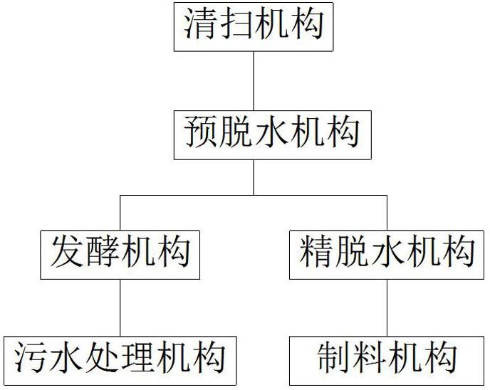
Fig. 1 is a schematic structural view of the present invention.
Fig. 2 is a schematic view of the sweeping mechanism of the present invention.
FIG. 3 is a schematic view of a cable retainer of the present invention.
Fig. 4 is a schematic view of a dung cleaning mechanism according to the invention.
FIG. 5 is a schematic view of a pre-dewatering mechanism of the present invention.
Fig. 6 is a schematic view of a biogas facility according to the present invention.
Fig. 7 is a schematic view of a fourth stirring mechanism of the present invention.
Fig. 8 is an exploded view of a third stirring mechanism of the present invention.
Fig. 9 is a schematic view of a second stirring mechanism of the present invention.
Fig. 10 is an exploded view of a second stirring mechanism of the present invention.
Fig. 11 is a schematic view of a first stirring mechanism of the present invention.
FIG. 12 is a schematic view of a wastewater treatment facility according to the present invention.
Fig. 13 is a schematic view of the stirring mechanism of the present invention.
FIG. 14 is a schematic view of the mixer of the present invention.
Fig. 15 is a schematic view of an aerator pipe of the present invention.
Fig. 16 is a schematic view of the freezing mechanism of the present invention.
FIG. 17 is a schematic view of the dewatering mechanism of the present invention.
Fig. 18 is a schematic view of the feed mechanism of the present invention.
In the figure: cleaning mechanism 1, steel cable fixer 2, feces cleaning mechanism 3, arc baffle 301, side plate 302, cleaning brush 303, universal wheel 304, cleaning mechanism 305, washing motor 306, motor 4, pre-dewatering mechanism 5, dewatering barrel 6, cow dung inlet 7, dewatering squeezing roller 8, first helical blade 9, cow dung outlet 10, support frame 11, dewatering motor 12, feces water outlet 13, circulating pump 14, water feeding pump 15, water feeding box 16, sewage stirring motor 17, stirring mechanism 18, stirrer 181, second gear 182, first gear 183, sewage treatment mechanism 19, aeration tank 20, blower 21, MBR membrane tank 22, aeration pipe 23, MBR module 24, sludge pump 25, control device 26, reclaimed water tank 27, biogas mechanism 28, protective shell 29, feces water pump 30, biogas stirring motor 31, feces water inlet 32, exhaust port 33, stirring mechanism 34, first stirring mechanism 341, aeration tank, sludge pump 25, control device 26, reclaimed water tank 27, biogas mechanism 28, protective shell 29, feces water pump 30, biogas stirring motor 31, feces water inlet 32, exhaust port 33, stirring mechanism 34, first stirring mechanism 341, cleaning brush mechanism, and sludge pump, The device comprises a second stirring mechanism 342, a driving tooth 3421, a driven tooth 3422, a speed change wheel 3423, a stirring wheel 3424, a third stirring mechanism 343, a fourth stirring mechanism 344, a slag liquid outlet 35, a slag discharge pump 36, a freezing mechanism 37, a cooling liquid outlet 38, a first motor 39, a conveying roller 40, a stirring barrel 41, a stirring rod 411, a frozen cow dung outlet 42, a second motor 43, a cooling liquid inlet 44, an air circulating pump 45, a dehydrated cow dung inlet 46, a heat insulation layer 47, a cooling pipe layer 471, a dehydrated stirring motor 48, a valve 49, a dehydrated inlet 50, a dehydrated mechanism 51, a vacuum pump 52, a first heating agent inlet 53, a heat insulation layer 54, a heating pipe layer 55, a heat dissipation layer 56, a stirring conveying roller 57, a second heating agent inlet 58, a second heating agent outlet 59, a first heating agent outlet 60, a dried cow dung outlet 61 and a preparation machine mechanism 62.
Detailed Description
For a better understanding of the present invention, reference will now be made to the following examples.
The following further describes embodiments of the present invention with reference to the drawings.
A cow dung treatment device is shown in figures 1-18 and comprises a cleaning mechanism 1, a pre-dewatering mechanism 5, a sewage treatment mechanism 19 and a fine dewatering mechanism, wherein the cleaning mechanism 1 is communicated with the pre-dewatering mechanism 5 through a sewer pipe, a methane mechanism 28 is arranged between the pre-dewatering mechanism 5 and the sewage treatment mechanism 19 and is communicated through a pipeline, the pre-dewatering mechanism 5 is communicated with the fine dewatering mechanism through a material conveying mechanism, and a material preparation mechanism 62 is arranged at a discharge outlet of the fine dewatering mechanism.
Cleaning mechanism 1 includes cable wire fixer 2 that is the rectangle and arranges, be equipped with the cable wire on cable wire fixer 2, be equipped with on the cable wire rather than fixed connection's clear excrement mechanism 3, still be equipped with motor 4 on the cable wire, clear excrement mechanism 3 includes cowl 301, cowl 301 both sides are equipped with curb plate 302, cowl 301 is last to be equipped with rather than fixed connection's washing mechanism 305, be equipped with washing brush motor 306 in the washing brush mechanism 305, be equipped with the cleaning brush 303 of being connected with washing brush motor 306 on the washing brush mechanism 305, be equipped with universal wheel 304 on the washing brush mechanism 3, still be equipped with water tank and nozzle in the washing brush mechanism 305.
The pre-dehydration mechanism 5 comprises a support frame 11, a dehydration barrel 6 is arranged on the support frame 11, a cow dung feeding hole 7 is arranged on the dehydration barrel 6, and a dung water outlet 13 is also arranged on the dehydration barrel 6; be equipped with dehydration squeeze roll 8 in the dehydration bucket 6, be equipped with first helical blade 9 on the dehydration squeeze roll 8, 6 one end of dehydration bucket is equipped with cow dung discharge gate 10, and the pitch of first helical blade 9 reduces from cow dung feed inlet 7 to cow dung discharge gate 10 direction gradually, is equipped with the dehydration motor 12 with the 8 hub connections of dehydration squeeze roll on the support frame 11.
The biogas mechanism 28 comprises a biogas tank, a protective shell 29 is arranged on the outer side of the biogas tank along the circumference, a biogas stirring motor 31 is arranged on the biogas tank, a liquid manure inlet 32 and an exhaust port 33 are arranged on the biogas tank, a liquid manure pump 30 communicated with the liquid manure inlet 32 is arranged on the biogas tank, and a water inlet of the liquid manure pump 30 is communicated with a liquid manure outlet 13; the stirring mechanism 34 connected with the biogas stirring motor 31 through a shaft is arranged in the biogas tank 28, the stirring mechanism 34 comprises a stirring shaft, the stirring shaft is sequentially provided with a first stirring mechanism 341, a second stirring mechanism 342, a third stirring mechanism 343 and a fourth stirring mechanism 344 from bottom to top, and the fourth stirring mechanism 344 is provided with three propelling blades.
The third stirring mechanism 343 comprises a driving tooth 3421 fixedly connected with the stirring shaft, the driving tooth 3421 is provided with a driven tooth 3422 engaged with the driving tooth 3422, the driven tooth 3422 is provided with a stirring wheel 3424 engaged with the driven tooth 3424, the stirring wheel 3424 is provided with four propelling paddles, the third stirring mechanism 343 further comprises a fixing clamp connected with the driven shaft and matched with the driven tooth 3422 and the stirring wheel 3424, the second stirring mechanism 342 comprises a driving tooth 3421 fixedly connected with the stirring shaft, the driving tooth 3421 is provided with a driven tooth 3422 engaged with the driving tooth 3421, the driven tooth 3422 is provided with a speed change wheel 3423 engaged with the driven tooth 3422, the speed change wheel 3423 is provided with a stirring wheel 3424 engaged with the speed change wheel 3423, the stirring wheel 3424 is provided with six propelling paddles, and the second stirring mechanism 342 further comprises a fixing clamp connected with the driven shaft and matched with the driven tooth 3422 and the stirring wheel 3424; the lower end of the methane tank is provided with a slag liquid outlet 35, and the slag liquid outlet 35 is provided with a slag pump 36 communicated with the slag liquid outlet.
The sewage treatment mechanism 19 comprises an aeration tank 20, an MBR membrane tank 22, a control device 26 and a reclaimed water tank 27, wherein a liquid inlet pipe communicated with a slag discharge pump 36 is arranged on the aeration tank 20, a water adding pump 15 communicated with the reclaimed water tank 27 is arranged on the liquid inlet pipe, a dosing tank 16 communicated with the aeration tank 20 is arranged on the aeration tank 20, a sewage stirring motor 17 is arranged on the aeration tank 20, and an air blower 21 is arranged on the aeration tank 20; the stirring mechanism 18 connected with the sewage stirring motor 17 is arranged in the aeration tank 20, the stirring mechanism 18 comprises a first gear 183, at least one stirrer 181 is meshed on the first gear 183, a second gear 182 is meshed on the stirrer 181, and at least one stirrer 181 is meshed on the second gear 182; a circulating pump 14 is arranged in the aeration tank 20, an aeration pipe 23 communicated with the circulating pump 14 and the air blower 21 is arranged in the aeration tank 20, and the aeration pipe 23 comprises an air pipe communicated with the air blower 21 and a water pipe communicated with the circulating pump 14.
Be equipped with the raceway between MBR membrane jar 22 and the aeration tank 20, be equipped with the valve on the raceway, be equipped with MBR module 24 in the MBR membrane jar 22, MBR module 24 lower extreme is equipped with the MBR membrane aeration pipe with air-blower 21 intercommunication, is equipped with the sludge pump 25 with aeration tank 20 intercommunication in the MBR membrane jar 22.
The fine dewatering mechanism comprises a freezing mechanism 37 and a dewatering mechanism 51, the freezing mechanism 37 comprises a refrigerating tank, a dewatered cow dung feeding hole 46 communicated with a cow dung discharging hole 10 is formed in the refrigerating tank, a frozen cow dung outlet 42 is formed in the refrigerating tank, a first motor 39 and a second motor 43 are arranged at two ends of the refrigerating tank, an air circulating pump 45 is arranged on the refrigerating tank, an air inlet of the air circulating pump 45 is communicated with one end of the refrigerating tank, and an air outlet of the air circulating pump 45 is communicated with the other end of the refrigerating tank; be equipped with the conveying roller 40 with 39 hub connections of first motor in the refrigeration jar, be equipped with the transport paddle leaf on the conveying roller 40, be equipped with the agitator 41 with the second motor 43 hub connection in the refrigeration jar, 41 internal face of agitator is equipped with the stirring rod 411 with conveying roller 40 matched with, be equipped with insulating layer 47 on the refrigeration jar internal surface, be equipped with the cooling tube layer 471 on the insulating layer 47, be equipped with coolant liquid import 44 and the coolant liquid export 38 with the cooling tube layer 471 intercommunication on the refrigeration jar.
The dehydration mechanism 51 comprises a dehydration tank, a dehydration stirring motor 48 is arranged on the dehydration tank, a stirring conveying roller 57 connected with the dehydration stirring motor 48 through a shaft is arranged in the dehydration tank, blades are arranged on the stirring conveying roller 57, a heating pipe layer 55 is arranged in the stirring conveying roller 57, and a second heating agent inlet 58 and a second heating agent outlet 59 which are communicated with the heating pipe layer 55 are arranged on the dehydration tank; be equipped with the vacuum pump 52 rather than the intercommunication on the drain sump, be equipped with the dehydration feed inlet 50 with freezing cow dung export 42 intercommunication on the drain sump, dehydration feed inlet 50 department is equipped with valve 49, be equipped with dry excrement discharge gate 61 on the drain sump, be equipped with heat preservation 54 in the drain sump, be equipped with heating tube layer 55 on the heat preservation 54, be equipped with first heating agent import 53 and first heating agent export 60 with heating tube layer 55 intercommunication on the drain sump, be equipped with heat dissipation layer 56 on the heating tube layer 55, system material mechanism 62 and dry excrement discharge gate 61 intercommunication.
When the device works, the motor 4 is started, the motor 4 drives the steel cable to move, the steel cable drives the dung cleaning mechanism 3 to carry out dung cleaning operation, the arc-shaped baffle plate 301 pushes cow dung on the ground to push a cow dung pipeline when the dung cleaning mechanism 3 moves, the washing electrode 306 works to drive the washing mechanism 305 to rotate to clean the ground in the process of pushing the cow dung, the nozzle sprays water to the ground, sewage flows into the cow dung pipeline along the groove of the steel cable, the clockwise or anticlockwise rotation of the motor 4 drives the dung cleaning mechanism 3 to carry out reciprocating motion to carry out dung removing and washing operation on the cowshed,
the cow dung is conveyed to the pre-dewatering mechanism 5 through a cow dung pipeline and enters the dewatering barrel 6 through a cow dung feeding hole 7, a dewatering motor 12 works to drive a dewatering squeeze roller 8 in the dewatering barrel 6 to rotate, a filter screen is arranged outside the dewatering squeeze roller 8, the cow dung separates water from the cow dung under the action of centrifugal force and extrusion, the water enters a sewage collecting mechanism below the dewatering squeeze roller 8 through the filter screen and is discharged through a dung water outlet 13, the dewatered cow dung is extruded by the dewatering squeeze roller 8 to form block-shaped dung and is discharged through a cow dung discharging hole 10,
the liquid dung discharged from the liquid dung outlet 13 enters the biogas mechanism 28 to ferment under the action of the liquid dung pump 30, the biogas stirring motor 31 of the biogas mechanism 28 operates to drive the first stirring mechanism 341, the second stirring mechanism 342, the third stirring mechanism 343 and the fourth stirring mechanism 344 to stir the liquid dung, the second stirring mechanism 342 enables the rotating speed of the stirring wheel 3424 to be lower under the action of the driven teeth 3422 and the change wheel 3423, the rotating speed of the stirring wheel 3424 of the third stirring mechanism 343 enables the rotating speed of the stirring wheel 3424 to be higher than that of the stirring wheel 3424 of the second stirring mechanism 342 under the action of the driven teeth 3422, the rotating speed of the fourth stirring mechanism 344 is the same as that of the stirring shaft without a speed reduction mechanism, and simultaneously, the liquid below the biogas mechanism 28 is more easily mixed with the upper solution due to the upward direction of the propelling type paddle, which is convenient for fermentation,
the fermented waste liquid enters the sewage treatment mechanism 19 through the residue discharge pump 36, when the waste liquid is thick, the reclaimed water in the reclaimed water tank 27 is mixed with the waste liquid through the water adding pump 15 to reduce the viscosity, the waste liquid enters the sewage treatment mechanism 19, then the waste liquid is subjected to oxygen exposure in the oxygen exposure tank 20, the sewage subjected to oxygen exposure treatment enters the MBR membrane tank 22 for treatment, the generated sludge is pumped out through the sludge pump 25 and sent into the oxygen exposure tank 20 or pumped out for dehydration and sent to a treatment plant for harmless treatment, the treated sewage is pumped into the reclaimed water tank 27,
cow dung dehydrated by the pre-dehydration mechanism 5 enters the freezing mechanism 37 through the dehydrated cow dung feeding hole 46, cooling liquid enters the cooling pipe layer 471 from the cooling liquid inlet 44 and is discharged from the cooling liquid outlet 38, the cooling liquid takes away heat in the refrigerating tank, meanwhile, the air circulating pump 45 works to enable air in the refrigerating tank to rapidly flow in the refrigerating tank to accelerate the loss of cow dung heat, the first motor 39 and the second motor 43 respectively drive the conveying roller 40 and the stirring barrel 41 to reversely rotate, the stirring rod 411 on the stirring barrel 41 stirs and scatters cow dung so as to facilitate freezing, and the frozen cow dung is discharged through the frozen cow dung outlet 42,
cow dung discharged from the frozen cow dung outlet 42 enters the dewatering mechanism 51 through the dewatering feed inlet 50, the dewatering stirring motor 48 drives the stirring conveying roller 57 to rotate to add the frozen cow dung into the dewatering mechanism 51 as much as possible, then the dewatering stirring motor 48 is powered off and stops working to close the valve 49, a heating agent enters the heating pipe layer 55 through the first heating agent inlet 53 and the second heating agent inlet 58 to heat the dewatering tank, meanwhile, the heating pipe layer 55 entering through the first heating agent inlet 53 is provided with the heat dissipation layer 56, the heat dissipation layer 56 accelerates heat transfer, the frozen cow dung in the dewatering tank is heated, reinforcing ribs are arranged in the heat insulation layer 54 of the dewatering tank to prevent the cow dung from being crushed by atmospheric pressure, the heating pipe layer 55 in the stirring conveying roller 57 heats the frozen cow dung, meanwhile, the vacuum pump 52 works to pump out gas in the dewatering tank, the pressure is reduced to ensure that ice in the cow dung sublimates to remove most of water, after sublimation is finished, the valve 49 is opened, the dehydration stirring motor 48 drives the stirring conveying roller 57 to rotate, dried cow dung is discharged to enter the material preparing mechanism 62 to be pressed into blocks, storage, transportation and subsequent reprocessing are facilitated, and environmental pollution is reduced.
It should be noted that, for those skilled in the art, many changes and modifications can be made without departing from the spirit and scope of the invention, and the invention is not to be considered limited to the embodiments illustrated in the above description.
- 上一篇:一种医用注射器针头装配设备
- 下一篇:一种高效污水处理设备