Adjustable retainer plate forming device of roll-like cake for food processing
阅读说明:本技术 一种食品加工用卷状糕点可调节定圈成型装置 (Adjustable retainer plate forming device of roll-like cake for food processing ) 是由 胡伟 于 2021-06-29 设计创作,主要内容包括:本发明公开了一种食品加工用卷状糕点可调节定圈成型装置,包括底座、成卷机构、传动机构和可调盛接机构,底座的顶部设置分切出料机构、承载板和安装架,承载板和安装架的底部均固定安装有支杆,支杆的一端与底座的顶部固定连接,成卷机构设于承载板的顶部,传动机构设于安装架的顶部。该食品加工用卷状糕点可调节定圈成型装置,能够对制作糕点的面团进行自动摊平处理,减轻操作人员的劳动负担,提升糕点制作的加工效率,能够将摊平的面皮自动成卷,便于精确掌握卷曲的圈数,还能够对摊平的面皮厚度进行调节,满足不同种类卷状糕点的制造要求。(The invention discloses an adjustable fixed-circle forming device for rolled cakes for food processing, which comprises a base, a rolling mechanism, a transmission mechanism and an adjustable containing and connecting mechanism, wherein the top of the base is provided with a slitting and discharging mechanism, a bearing plate and an installation frame, the bottoms of the bearing plate and the installation frame are both fixedly provided with a supporting rod, one end of the supporting rod is fixedly connected with the top of the base, the rolling mechanism is arranged at the top of the bearing plate, and the transmission mechanism is arranged at the top of the installation frame. This adjustable solid fixed ring forming device of roll-like cake for food processing can carry out automatic shakeout processing to the dough of preparation cake, alleviates operating personnel's work burden, promotes the machining efficiency of cake preparation, can be with the automatic lapping of the face skin of shakeout, the accurate number of turns of curling of mastering of being convenient for, can also adjust the face skin thickness of shakeout, satisfies the manufacturing requirement of different kinds of roll-like cake.)
1. The utility model provides an adjustable circle forming device of deciding of roll-like cake for food processing which characterized in that includes:
the cutting and discharging device comprises a base (1), wherein a cutting and discharging mechanism (5), a bearing plate (7) and an installation frame (8) are arranged at the top of the base (1), supporting rods are fixedly arranged at the bottoms of the bearing plate (7) and the installation frame (8), and one ends of the supporting rods are fixedly connected with the top of the base (1);
the coiling mechanism (2) is arranged at the top of the bearing plate (7);
the transmission mechanism (3) is arranged at the top of the mounting rack (8);
the adjustable containing and connecting mechanism (4) is connected with the bearing plate (7).
2. The adjustable fixed ring forming device of rolled cake for food processing as claimed in claim 1, wherein: the coiling mechanism (2) comprises a coiling rod (201), a transmission gear (202), a main screw rod (203) and a first motor (204), a movable opening is formed in the bearing plate (7), an installation slide rail is fixedly installed in the movable opening, a slide block is installed on the slide rail in a sliding mode, an installation block is arranged in the movable opening and fixedly installed on the slide block, the coiling rod (201) is installed on the front side of the installation block in a rotating mode, one end of the coiling rod (201) penetrates through the movable opening to extend to the rear side of the bearing plate (7) and is fixedly provided with the transmission gear (202), a connecting block is fixedly installed at the top of the installation block and is located on the rear side of the bearing plate (7), two groups of support plates are fixedly installed on the rear side of the bearing plate (7), the main screw rod (203) is installed between the two groups of support plates in a rotating mode, the connecting block is installed on the main screw rod (203), the first motor (204) is fixedly installed on the outer wall of one side of each support plate, an output shaft of the first motor (204) is fixedly connected with one end of the main screw rod (203) through a coupler.
3. The adjustable fixed ring forming device of rolled cake for food processing as claimed in claim 2, wherein: drive mechanism (3) are including activity diaphragm (301), transmission pinion rack (302), vice lead screw (303) and second motor (304), the inside of mounting bracket (8) is provided with activity diaphragm (301), the top fixed mounting of activity diaphragm (301) has transmission pinion rack (302), transmission pinion rack (302) meshes with drive gear (202) mutually, activity diaphragm (301) and mounting bracket (8) slidable mounting, it installs vice lead screw (303) to rotate on the one side inner wall of mounting bracket (8), the thread groove has been seted up on activity diaphragm (301), vice lead screw (303) are through thread groove and activity diaphragm (301) threaded mounting, fixed mounting has second motor (304) on the outer wall of one side of mounting bracket (8), the output shaft of second motor (304) and the one end fixed connection of vice lead screw (303).
4. The adjustable retainer forming device for rolled confectionery in accordance with claim 1, 2 or 3, wherein: adjustable connecing mechanism (4) greatly includes mounting bracket (401), connect board (402) greatly, threaded rod (403) and guide bar (404), the top fixed mounting of base (1) has mounting bracket (401), three mounting holes of group have been seted up at the top of mounting bracket (401), there are a set of screw sleeve pipe and two sets of sleeve pipes in three mounting holes fixed mounting respectively, threaded rod (403) are installed to screw sleeve pipe internal thread, the cover pipe endotheca is established and is installed guide bar (404), the upper end of threaded rod (403) is rotated the installation with the bottom of receiving board (402), the upper end of guide bar (404) and the bottom fixed connection of receiving board (402), the other end fixed mounting of threaded rod (403) has manual wheel.
5. The adjustable fixed ring forming device of rolled cake for food processing as claimed in claim 4, wherein: the top of loading board (7) is fixed with dust hood (6), and dust hood (6) is located directly over holding board (402).
6. The adjustable fixed ring forming device of rolled cake for food processing as claimed in claim 4, wherein: the front side of the bearing plate (7) is provided with a scale label.
7. The adjustable fixed ring forming device of rolled cake for food processing as claimed in claim 1, wherein: the slitting and discharging mechanism (5) comprises an L-shaped rod (501), a mounting sleeve (502), slitting blades (503), movable sliding rods (504), supporting blocks (505) and a sliding pipe (506), the top of the base (1) is fixedly provided with the L-shaped rod (501), the L-shaped rod (501) is movably sleeved with the mounting sleeve (502), the outer wall of the mounting sleeve (502) is fixedly provided with two groups of mounting plates, two groups of movable sliding rods (504) are fixedly arranged between the two groups of mounting plates, the two groups of movable sliding rods (504) are respectively sleeved with a plurality of groups of supporting blocks (505) and a plurality of groups of sliding pipes (506), the supporting blocks (505) are fixedly connected with the sliding pipe (506), one side of the mounting sleeve (502) is provided with the plurality of groups of slitting blades (503), the slitting blades (503) are fixedly connected with the supporting blocks (505), the outer wall of the sliding pipe (506) is provided with threaded holes, and fastening bolts are arranged in the threaded holes, one end of the fastening bolt is jointed with the outer wall of the movable sliding rod (504).
8. The adjustable fixed ring forming device of rolled cake for food processing as claimed in claim 7, wherein: the outer wall of the installation sleeve (502) is fixedly provided with a handle, the outer wall of the L-shaped rod (501) and the front end of the installation sleeve (502) are fixedly provided with limit blocks, and the two sets of limit blocks are attached to each other.
Technical Field
The invention relates to the technical field of food processing, in particular to a coiled cake fixed-ring forming device for food processing.
Background
When the rolled cakes are manufactured, dough needs to be spread firstly, and then the rolled cakes are manufactured through the processes of curling, cutting, baking and the like, but most cake manufacturing devices on the market are inconvenient to manufacture the rolled cakes at present, the practicability is poor, the thickness of the rolled cakes and the width of cutting and forming are inconvenient to adjust, for example, a patent with the publication number of CN108576109A is poor in flexibility, the requirements of manufacturing different kinds of cakes are difficult to meet, and the popularization and the use are not facilitated.
Disclosure of Invention
The invention aims to solve at least one technical problem in the prior art, and provides an adjustable fixed-circle forming device for rolled pastries for food processing, which can solve the problem that the thickness of the rolled pastries and the width of cut forming are inconvenient to adjust.
In order to achieve the purpose, the invention provides the following technical scheme: an adjustable circle forming device of web-like cake for food processing, it includes: the cutting and discharging mechanism, the loading plate and the mounting frame are arranged at the top of the base, supporting rods are fixedly mounted at the bottoms of the loading plate and the mounting frame, and one end of each supporting rod is fixedly connected with the top of the base; the coiling mechanism is arranged at the top of the bearing plate; the transmission mechanism is arranged at the top of the mounting frame; the adjustable containing and connecting mechanism is connected with the bearing plate.
Preferably, the coiling mechanism comprises a coiling rod, a transmission gear, a main screw rod and a first motor, a movable opening is formed in the bearing plate, an installation slide rail is fixedly installed in the movable opening, a slide block is installed on the slide rail in a sliding mode, an installation block is arranged in the movable opening, the installation block is fixedly installed on the slide block, the front side of the installation block is rotatably installed with the coiling rod, one end of the coiling rod penetrates through the movable opening and extends to the rear side of the bearing plate, the transmission gear is fixedly installed on the rear side of the bearing plate, a connecting block is fixedly installed at the top of the installation block and is located at the rear side of the bearing plate, two groups of support plates are fixedly installed at the rear side of the bearing plate, the main screw rod is rotatably installed between the two groups of support plates, the connecting block is in threaded installation on the main screw rod, the first motor is fixedly installed on the outer wall of one side of the support plates, and the output shaft of the first motor is fixedly connected with one end of the main screw rod through a coupler.
Preferably, drive mechanism includes the activity diaphragm, the transmission pinion rack, vice lead screw and second motor, the inside of mounting bracket is provided with the activity diaphragm, the top fixed mounting of activity diaphragm has the transmission pinion rack, the transmission pinion rack meshes with drive gear mutually, activity diaphragm and mounting bracket slidable mounting rotate on one side inner wall of mounting bracket and install vice lead screw, the thread groove has been seted up on the activity diaphragm, vice lead screw passes through thread groove and activity diaphragm threaded mounting, fixed mounting has the second motor on one side outer wall of mounting bracket, the output shaft of second motor and the one end fixed connection of vice lead screw.
Preferably, adjustable connecing mechanism greatly includes mounting bracket, splendid attire board, threaded rod and guide bar, and the top fixed mounting of base has the mounting bracket, and three mounting holes of group have been seted up at the top of mounting bracket, and fixed mounting has a set of screw sleeve pipe and two sets of sleeve pipes respectively in three mounting holes, and screw sleeve pipe internal thread installs the threaded rod, and the cover pipe endotheca is established and is installed the guide bar, and the installation is rotated with the bottom of splendid attire board to the upper end of threaded rod, the upper end of guide bar and the bottom fixed connection who connects the board greatly, and the other end fixed mounting of threaded rod has manual wheel.
Preferably, the top of the bearing plate is fixedly provided with a dust hood, and the dust hood is positioned right above the containing plate.
Preferably, the front side of the bearing plate is provided with a scale label.
Preferably, cut discharge mechanism and include L shape pole, the installation sleeve pipe, the slitting blade, the activity slide bar, prop up piece and slip pipe, the top fixed mounting of base has L shape pole, movable sleeve is equipped with the installation sleeve pipe on the L shape pole, fixed mounting has two sets of mounting panels on the outer wall of installation sleeve pipe, fixed mounting has two sets of activity slide bars between two sets of mounting panels, overlap respectively on two sets of activity slide bars and establish and install multiunit piece and multiunit slip pipe, prop up piece and slip pipe fixed connection, one side of installation sleeve pipe is provided with multiunit slitting blade, slitting blade and piece fixed connection, set up threaded hole on the outer wall of slip pipe, threaded hole installs fastening bolt, fastening bolt's one end is laminated mutually with the outer wall of activity slide bar.
Preferably, the outer wall of the installation sleeve is fixedly provided with a handle, the outer wall of the L-shaped rod and the front end of the installation sleeve are fixedly provided with limit blocks, and the two groups of limit blocks are attached to each other.
Compared with the prior art, the invention has the beneficial effects that:
(1) the utility model discloses a dough making device, including main lead screw, drive gear, main lead screw and first motor, can carry out automatic shakeout to the dough of preparation cake and handle, the follow-up lapping operation of being convenient for, hoisting device's practicality and an organic whole nature, alleviate operating personnel's work burden, promote the machining efficiency of cake preparation, in addition, the activity diaphragm, the transmission pinion rack, the cooperation of vice lead screw and second motor is used, can be with the automatic lapping of the face skin of shakeout, the accurate number of turns of curling of mastering of being convenient for, drive gear and activity diaphragm reach integrative multi-purpose effect, reduce the holistic cost of device and running cost.
(2) The wrapper thickness of flattening can be adjusted by matching the winding rod, the mounting frame, the containing plate and the threaded rod, so that the thickness of the rolled cakes is changed, the manufacturing requirements of different kinds of rolled cakes are met, the use scene and range of the device are widened, the adjusting mode is simple, and the use is convenient.
(3) The utility model discloses a dough forming device, through L shape pole, the installation sleeve pipe, the slitting blade, the activity slide bar, the cooperation of piece and slip tube is used, can cut the face skin after the lapping, can change the distance between every group slitting blade simultaneously, thereby can adjust the width of shaping web cake according to actual preparation demand, further promote the device's flexibility, the dough cover after the cutting is located on the cover winding stem, can follow the separation of dough from the cover winding stem through promoting L shape pole, the ejection of compact is swift convenient, promote production machining efficiency, promote in-service use and experience.
Drawings
The invention is further illustrated with reference to the following figures and examples:
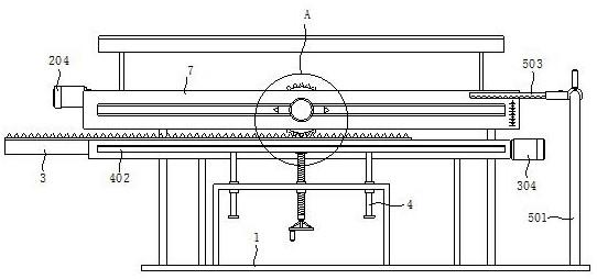
FIG. 1 is a front view of the present invention;
FIG. 2 is a rear view of the present invention;
FIG. 3 is an enlarged view of portion A of the present invention;
FIG. 4 is a schematic view of the internal structure of the mount of the present invention;
FIG. 5 is a top view of the L-shaped pole of the present invention;
FIG. 6 is an enlarged view of the portion B of the present invention.
In the figure: the automatic winding machine comprises a base 1, a winding mechanism 2, a winding rod 201, a transmission gear 202, a main lead screw 203, a first motor 204, a transmission mechanism 3, a movable transverse plate 301, a transmission toothed plate 302, an auxiliary lead screw 303, a second motor 304, an adjustable receiving mechanism 4, a mounting rack 401, a receiving plate 402, a threaded rod 403, a guide rod 404, a slitting and discharging mechanism 5, an L-shaped rod 501, a mounting sleeve 502, a slitting blade 503, a movable sliding rod 504, a supporting block 505, a sliding pipe 506, a dust hood 6, a bearing plate 7 and a mounting rack 8.
Detailed Description
Reference will now be made in detail to the present preferred embodiments of the present invention, examples of which are illustrated in the accompanying drawings, wherein like reference numerals refer to like elements throughout.
In the description of the present invention, it should be understood that the orientation or positional relationship referred to in the description of the orientation, such as the upper, lower, front, rear, left, right, etc., is based on the orientation or positional relationship shown in the drawings, and is only for convenience of description and simplification of description, and does not indicate or imply that the device or element referred to must have a specific orientation, be constructed and operated in a specific orientation, and thus, should not be construed as limiting the present invention.
In the description of the present invention, greater than, less than, exceeding, etc. are understood as excluding the present numbers, and the above, below, inside, etc. are understood as including the present numbers. If the first and second are described for the purpose of distinguishing technical features, they are not to be understood as indicating or implying relative importance or implicitly indicating the number of technical features indicated or implicitly indicating the precedence of the technical features indicated.
In the description of the present invention, unless otherwise explicitly limited, terms such as arrangement, installation, connection and the like should be understood in a broad sense, and those skilled in the art can reasonably determine the specific meanings of the above terms in the present invention in combination with the specific contents of the technical solutions.
Referring to fig. 1-6, the present invention provides a technical solution: the utility model provides an adjustable circle forming device that decides of roll-like cake for food processing, including base 1, lapping mechanism 2, drive mechanism 3 and adjustable connecing mechanism 4 greatly, discharge mechanism 5 is cut in base 1's top setting, loading board 7 and mounting bracket 8, the equal fixed mounting in bottom of loading board 7 and mounting bracket 8 has branch, the one end of branch and base 1's top fixed connection, lapping mechanism 2 locates the top of loading board 7, drive mechanism 3 locates the top of mounting bracket 8, adjustable connecing mechanism 4 greatly is connected with loading board 7.
The coiling mechanism 2 comprises a coiling rod 201 and a transmission gear 202, the main screw 203 and the first motor 204, an activity entrance to a cave has been seted up on the loading board 7, the fixed mounting has the installation slide rail in the activity entrance to a cave, slidable mounting has the slider on the slide rail, be provided with the installation piece in the activity entrance to a cave, installation piece fixed mounting is on the slider, the front side of installation piece is rotated and is installed cover winding stem 201, the one end of cover winding stem 201 passes the activity entrance to a cave and extends to the rear side of loading board 7 and fixed mounting has drive gear 202, the top fixed mounting of installation piece has the connecting block, the connecting block is located the rear side of loading board 7, the rear side fixed mounting of loading board 7 has two sets of extension boards, rotate between two sets of extension boards and install main screw 203, connecting block threaded mounting is on main screw 203, fixed mounting has first motor 204 on the outer wall of one side of extension board, the output shaft of first motor 204 passes through the one end fixed connection of shaft coupling and main screw 203.
Drive mechanism 3 includes activity diaphragm 301, transmission pinion rack 302, vice lead screw 303 and second motor 304, the inside of mounting bracket 8 is provided with activity diaphragm 301, the top fixed mounting of activity diaphragm 301 has transmission pinion rack 302, transmission pinion rack 302 meshes with drive gear 202 mutually, the equal fixed mounting in front and back side of activity diaphragm 301 has a set of slider, equal fixed mounting has a set of slide rail on the front and back side inner wall of mounting bracket 8, slider slidable mounting is on the slide rail, activity diaphragm 301 and 8 slidable mounting of mounting bracket, rotate on one side inner wall of mounting bracket 8 and install vice lead screw 303, the thread groove has been seted up on the activity diaphragm 301, vice lead screw 303 passes through thread groove and activity diaphragm 301 threaded mounting, fixed mounting has second motor 304 on the outer wall of one side of mounting bracket 8, the output shaft of second motor 304 and the one end fixed connection of vice lead screw 303.
Adjustable flourishing mechanism 4 includes mounting bracket 401, flourishing fishplate bar 402, threaded rod 403 and guide bar 404, base 1's top fixed mounting has mounting bracket 401, three mounting holes of group have been seted up at mounting bracket 401's top, there are a set of screw sleeve pipe and two sets of sleeve pipes in three mounting holes fixed mounting respectively, screw sleeve pipe internal thread installs threaded rod 403, the guide bar 404 is installed to the cover pipe endotheca is established, the upper end of threaded rod 403 and the bottom rotation installation that connects fishplate bar 402 greatly, the upper end of guide bar 404 and the bottom fixed connection who connects fishplate bar 402 greatly, the other end fixed mounting of threaded rod 403 has manual wheel, the top fixed mounting of loading board 7 has dust cover 6, dust cover 6 is located flourishing fishplate bar 402 directly over, the front side of loading board 7 is provided with the scale label.
The slitting and discharging mechanism 5 comprises an L-shaped rod 501, a mounting sleeve 502, a slitting blade 503, movable sliding rods 504, a supporting block 505 and a sliding pipe 506, the top of a base 1 is fixedly provided with the L-shaped rod 501, the L-shaped rod 501 is movably sleeved with the mounting sleeve 502, the outer wall of the mounting sleeve 502 is fixedly provided with two groups of mounting plates, two groups of movable sliding rods 504 are fixedly mounted between the two groups of mounting plates, the two groups of movable sliding rods 504 are respectively sleeved with a plurality of groups of supporting blocks 505 and a plurality of groups of sliding pipes 506, the supporting blocks 505 are fixedly connected with the sliding pipes 506, one side of the mounting sleeve 502 is provided with the multi-group slitting blade 503, the slitting blade 503 is fixedly connected with the supporting blocks 505, the outer wall of the sliding pipe 506 is provided with threaded holes, fastening bolts are mounted in the threaded holes, one ends of the fastening bolts are attached to the outer wall of the movable sliding rods 504, the outer wall of the mounting sleeve 502 is fixedly provided with a handle, the outer wall of the L-shaped rod 501 and the front end of the mounting sleeve 502 are both fixedly provided with limiting blocks, the two groups of limiting blocks are attached to each other.
The working principle is as follows: the dough to be paved is placed on the receiving plate 402, the manual wheel is shaken to drive the threaded rod 403 to rotate, the receiving plate 402 moves longitudinally under the driving of the threaded rod 403 and the guiding action of the guide rod 404, the distance between the receiving plate 402 and the winding rod 201 changes accordingly, and the distance between the receiving plate 402 and the winding rod 201 is determined according to the manufacturing requirement and the scale label; the first motor 204 is controlled to be started to drive the main lead screw 203 to rotate, the connecting block transversely moves under the driving of the main lead screw 203 and the guiding action of the bearing plate 7, the transmission gear 202 transversely moves along with the connecting block, the transmission gear 202 starts to rotate under the meshing transmission action of the transmission toothed plate 302 to pave dough, after the dough is paved into dough sheets, the first motor 204 is controlled to reversely shake the manual wheel, the containing and connecting plate 402 descends along with the manual wheel, and one edge of the dough sheets is wound on the winding rod 201; controlling a second motor 304 to start, enabling an auxiliary screw rod 303 to rotate along with the auxiliary screw rod, enabling a movable transverse plate 301 to transversely move under the driving of the auxiliary screw rod 303 and the limiting effect of an installation frame 8, enabling a transmission toothed plate 302 to transversely move along with the auxiliary screw rod, enabling a transmission gear 202 to rotate along with the auxiliary screw rod, enabling the wrapper to start to be wound on a winding rod 201, moving the winding rod 201 to the position below a slitting blade 503 after winding is completed, enabling the slitting blade 503 to be lapped on dough after being turned over, cutting the wrapper, enabling the wrapper to continuously rotate, and enabling the slitting blade 503 to cut the wrapper into rolls; the fastening bolts on the sliding pipes 506 are unscrewed, the support blocks 505 and the sliding pipes 506 can move on the movable sliding rods 504, the distance between the two adjacent groups of cutting blades 503 is adjusted according to the width requirement of cake coiling, after cutting, the mounting sleeve 502 is pushed by the handle, and the cut dough sheets fall down from the coiling rod 201, so that the discharging is completed.
The embodiments of the present invention have been described in detail with reference to the accompanying drawings, but the present invention is not limited to the above embodiments, and various changes can be made within the knowledge of those skilled in the art without departing from the gist of the present invention.
- 上一篇:一种医用注射器针头装配设备
- 下一篇:一种牦牛奶渣饼生产系统