Intelligent control hidden computer type office table
阅读说明:本技术 一种智能调控隐藏电脑式办公桌 (Intelligent control hidden computer type office table ) 是由 陈国华 于 2021-08-06 设计创作,主要内容包括:本发明公开了一种智能调控隐藏电脑式办公桌,包括桌体,桌体内部具有一存储室,存储室中具有调控机构。调控机构包括旋转座、安装座和对称设置的支撑板、盖板、传送带、挡板。该办公桌结构设计紧凑,能够通过一键将显示器隐藏或者调出,方便办公。增大了人们工作时的办公空间。而且当显示器不用时可将其隐藏在桌面内部,使桌面更加整洁、且可利用空间更大,提高了办公桌的利用率。(The invention discloses an intelligent control hidden computer type office table which comprises a table body, wherein a storage chamber is arranged in the table body, and a control mechanism is arranged in the storage chamber. The regulating mechanism comprises a rotating seat, a mounting seat, and a supporting plate, a cover plate, a conveying belt and a baffle plate which are symmetrically arranged. This desk structural design is compact, can hide the display or call out through a key, makes things convenient for official working. The office space of people during work is enlarged. And when the display is not used, the display can be hidden in the desktop, so that the desktop is tidier, the available space is larger, and the utilization rate of the office desk is improved.)
1. An intelligent control hidden computer type office table comprises a table body and is characterized in that a storage chamber is arranged in the table body, and a control mechanism is arranged in the storage chamber;
the regulating mechanism comprises a rotating seat, a mounting seat, and symmetrically arranged supporting plates, a cover plate, a conveyor belt and a baffle plate, wherein the supporting plates are vertically arranged in the storage chamber, the symmetrically arranged supporting plates are connected through a rotating rod, two ends of the rotating rod are provided with first gears, the rotating seat is arranged in the middle of the rotating rod, the mounting seat is vertically arranged on the rotating seat, the conveyor belt is vertically arranged in the storage chamber, the middle of two ends of the conveyor belt is provided with a rotating shaft, two ends of the rotating shaft are arranged on the inner wall of the storage chamber, the rotating shaft at the lower end of the middle of the conveyor belt is provided with a first motor, the first motor is arranged in the storage chamber, the conveyor belt is provided with a first hinge part, the lower end of the cover plate is provided with a second hinge part, the first hinge part is connected with the second hinge part through a hinge rod, and the inner wall of the cover plate is provided with a vertical groove, the vertical groove is provided with teeth, a placing chamber for placing the cover plate is arranged between the baffle plate and the conveyor belt, the upper end of the storing chamber is provided with a through hole for placing the cover plate, a ring wall of the through hole is provided with a storing chamber, and a push-pull plate is arranged in the storing chamber.
2. The intelligent control hidden computer type office table as claimed in claim 1, wherein a dovetail block is arranged at the lower end of the mounting base, a dovetail groove is arranged on the rotating base, the dovetail block is arranged in the dovetail groove in a matched mode, and a fastening bolt is arranged on the dovetail block.
3. The intelligent control hidden computer type office table as claimed in claim 1, wherein the inner wall of the storage chamber is provided with a second motor, a first supporting block and a second supporting block, the second motor is provided with a motor rod, the motor rod is provided with a second gear and a belt, the first supporting block is provided with a first rotating rod, the second supporting block is provided with a second rotating rod, the first rotating rod is provided with a first pushing block, the second rotating rod is provided with a second pushing block and a third gear, one end of the belt is installed on the first rotating rod, the other end of the belt is connected with the first rotating rod, and the second gear is meshed with the third gear.
4. The intelligent control hidden computer type office desk as claimed in claim 3, wherein the inner wall of the storage room is further provided with symmetrically arranged support blocks, and the first pushing block and the second pushing block are respectively arranged on different support blocks.
5. The intelligent control hidden computer type office table as claimed in claim 1, wherein the inner wall of the cover plate is provided with symmetrically arranged guide parts, the guide parts are provided with guide arc surfaces, and a gap is formed between the guide parts.
6. The intelligent control hidden computer desk as recited in claim 1, wherein the push-pull plate has symmetrically arranged extensions and a push-pull portion for pulling the push-pull plate.
Technical Field
The invention relates to the technical field of office tables, in particular to an intelligent control hidden computer type office table.
Background
The computer is one of the common tools for people, and is generally placed on a computer desk or an office desk, especially a desktop display is fixedly placed, or the whole computer desk is occupied, and the office desk display also occupies most space of the computer desk, so that when other works are needed, such as drawing or writing reports, the work can only be processed by other vacant office desks.
Therefore, the invention designs the intelligent control hidden computer type office table, when a computer is used, the display is placed on the table top, and when the computer is used, the display is hidden, and the office table can be used as a normal working table.
Disclosure of Invention
In order to overcome the defects in the prior art, the invention provides an intelligent control hidden computer type office table.
The technical scheme of the invention is realized as follows:
an intelligent control hidden computer type office table comprises a table body and is characterized in that a storage chamber is arranged in the table body, and a control mechanism is arranged in the storage chamber;
the regulating mechanism comprises a rotating seat, a mounting seat, and symmetrically arranged supporting plates, a cover plate, a conveyor belt and a baffle plate, wherein the supporting plates are vertically arranged in the storage chamber, the symmetrically arranged supporting plates are connected through a rotating rod, two ends of the rotating rod are provided with first gears, the rotating seat is arranged in the middle of the rotating rod, the mounting seat is vertically arranged on the rotating seat, the conveyor belt is vertically arranged in the storage chamber, the middle of two ends of the conveyor belt is provided with a rotating shaft, two ends of the rotating shaft are arranged on the inner wall of the storage chamber, the rotating shaft at the lower end of the middle of the conveyor belt is provided with a first motor, the first motor is arranged in the storage chamber, the conveyor belt is provided with a first hinge part, the lower end of the cover plate is provided with a second hinge part, the first hinge part is connected with the second hinge part through a hinge rod, and the inner wall of the cover plate is provided with a vertical groove, the vertical groove is provided with teeth, a placing chamber for placing the cover plate is arranged between the baffle plate and the conveyor belt, the upper end of the storing chamber is provided with a through hole for placing the cover plate, a ring wall of the through hole is provided with a storing chamber, and a push-pull plate is arranged in the storing chamber.
In the invention, the lower end of the mounting seat is provided with a dovetail block, the rotary seat is provided with a dovetail groove, the dovetail block is arranged in the dovetail groove in a matching way, and the dovetail block is provided with a fastening bolt.
According to the invention, the inner wall of the storage chamber is provided with a second motor, a first supporting block and a second supporting block, the second motor is provided with a motor rod, the motor rod is provided with a second gear and a belt, the first supporting block is provided with a first rotating rod, the second supporting block is provided with a second rotating rod, the first rotating rod is provided with a first pushing block, the second rotating rod is provided with a second pushing block and a third gear, one end of the belt is installed on the first rotating rod, the other end of the belt is connected with the first rotating rod, and the second gear is meshed with the third gear.
In the invention, the inner wall of the storage chamber is also provided with symmetrically arranged support blocks, and the first pushing block and the second pushing block are respectively arranged on different support blocks.
In the invention, the inner wall of the cover plate is provided with guide parts which are symmetrically arranged, the guide parts are provided with guide arc surfaces, and a gap is formed between the guide parts.
In the invention, the push-pull plate is provided with symmetrically arranged extension parts and a push-pull part for pulling the push-pull plate.
The intelligent control hidden computer type office table has the following beneficial effects: this desk structural design is compact, can hide the display or call out through a key, makes things convenient for official working. The office space of people during work is enlarged. And when the display is not used, the display can be hidden in the desktop, so that the desktop is tidier, the available space is larger, and the utilization rate of the office desk is improved.
Drawings
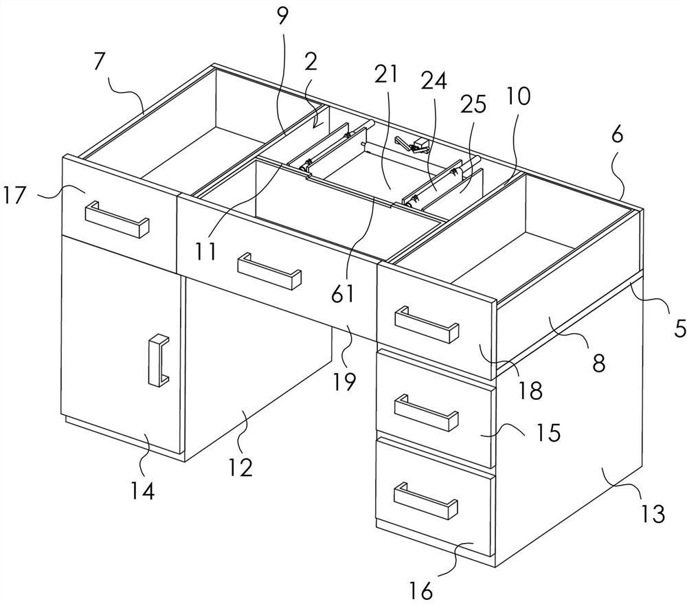
FIG. 1 is a schematic view of an intelligent control hidden computer type office desk according to the present invention;
FIG. 2 is a top view of FIG. 1;
FIG. 3 is a cross-sectional view taken along line A-A of FIG. 2;
FIG. 4 is a schematic structural view of the upper plate, the lower plate, the left support plate and the right support plate of FIG. 1;
FIG. 5 is a schematic view of the internal structure of FIG. 4;
FIG. 6 is a schematic view of the internal structure of FIG. 5;
FIG. 7 is another schematic view of the inverted structure of FIG. 6;
FIG. 8 is a partial enlarged view of FIG. 7 at B;
FIG. 9 is a front view of FIG. 6;
FIG. 10 is a top view of FIG. 7;
FIG. 11 is a cross-sectional view taken at C-C of FIG. 10;
FIG. 12 is a schematic view of the internal structure of FIG. 7;
FIG. 13 is a schematic view of the rotary base and the mounting base of FIG. 12;
FIG. 14 is a schematic view of the cover plate of FIG. 6;
FIG. 15 is a schematic view of the internal structure of FIG. 1;
FIG. 16 is a back view of the upper plate of FIG. 1;
FIG. 17 is an enlarged view of a portion of FIG. 16 at D;
FIG. 18 is an exploded view of the push-pull plate and the upper plate of FIG. 16;
FIG. 19 is a reference view of the cover plate rotated to the vertical position in the present invention;
fig. 20 is a reference diagram of the use state of the intelligent control hidden computer desk of the present invention.
Detailed Description
The technical solution in the embodiments of the present invention will be clearly and completely described below with reference to the accompanying drawings in the embodiments of the present invention.
As shown in fig. 1 to 20, the intelligent control hidden computer type office table of the present invention includes a table body 1, a storage chamber 2 is provided inside the table body 1, and a control mechanism 3 is provided in the storage chamber 2.
The table body 1 is composed of an upper plate 4, a lower plate 5, a rear plate 6, a left plate 7 and a right plate 8, a left support plate 9 and a right support plate 10 are further arranged between the upper plate 4 and the lower plate 5, the left support plate 9 and the right support plate 10 are located between the left plate 7 and the right plate 8, and a partition plate 11 is further arranged between the left support plate 9 and the right support plate 10. Meanwhile, the lower end of the lower plate 5 is provided with a first cabinet body 12 and a second cabinet body 13, the first cabinet body 12 and the second cabinet body 13 are symmetrically arranged, a space for placing legs of an office is reserved in the middle, the first cabinet body 12 is provided with a rotary door plate 14, and the first cabinet body 12 is provided with a first drawer 15 and a second drawer 16. Meanwhile, a left drawer 17 is arranged between the left plate 7 and the left support plate 9, a right drawer 18 is arranged between the right plate 8 and the right support plate 10, and a middle drawer 19 is arranged between the left support plate 9, the right support plate 10 and the partition plate 11. Wherein the length of the middle drawer 19 is only half the width of the upper plate 4.
The partition plate 11, the left support plate 9, the right support plate 10, the upper plate 4 and the rear plate 6 form a storage chamber 2 therebetween.
Of course, the middle drawer 19 may be a drawing keyboard plate for placing a keyboard.
The regulating mechanism 3 comprises a rotating seat 20, a mounting seat 21, a supporting plate 22, a cover plate 23, a conveyor belt 24 and a baffle plate 25 which are symmetrically arranged. Wherein, roating seat 20 and mount pad 21 are located the centre of the backup pad 22 of symmetry setting, and the backup pad 22 of symmetry setting is located between the conveyer belt 24 of symmetry setting, and the conveyer belt 24 of symmetry setting is located between the baffle 25 of symmetry setting.
The vertical installation of backup pad 22 is in locker room 2, and the backup pad 22 that the symmetry set up is connected through rotary rod 26 between, and the both ends of rotary rod 26 have first gear 27, and roating seat 20 is installed in the centre of rotary rod 26, and the mount pad 21 vertically is installed on roating seat 20, and the vertical installation of conveyer belt 24 is in locker room 2. The conveyor belt 24 has a rotation shaft 28 in the middle of both ends thereof, both ends of the rotation shaft 28 are installed on the inner wall of the storage chamber 2, and both ends of the rotation shaft 28 are installed at the partition plate 11 at one end and at the rear plate 6 at the other end. The rotating shaft 28 at the middle lower end of the conveyor belt 24 is provided with a first motor 29, and the first motor 29 is installed in the storage chamber 2 and can drive the conveyor belt 24 to rotate when the first motor 29 rotates. Since the first motor 29 has two positions, the two positions of the first motor 29 rotate simultaneously when the motor is started.
The conveyor belt 24 is provided with a first hinge part 30, the lower end of the cover plate 23 is provided with a second hinge part 31, and the first hinge part 30 and the second hinge part 31 are connected through a hinge rod 32.
The cover plate 23 has a vertical slot 33 on the inner wall, the vertical slot 33 has teeth 34 therein, the teeth 34 in the vertical slot 33 are located in the upper half of the vertical slot 33, and the lower half is not provided with the teeth 34, the number of the teeth 34 is set according to the angle of rotation of the rotating rod 26, and when the rotating rod 26 rotates 90 °, the teeth 34 which only allow the rotating rod 26 to rotate 90 ° can be provided.
The lower half of the vertical groove 33 without the teeth 34 is formed by lifting one end of the cover plate 23, the lifted end being located at the middle end of the two cover plates 23, and then gradually rotating from a horizontally disposed state to a vertically disposed state after being lifted by the end of the cover plate 23. When rotating to the state of vertical setting, first gear 27 is in the vertical slot 33 portion that does not have tooth 34, when apron 23 rotates to the state of vertical setting, first gear 27 is convenient for tooth 34 to have contacted, then when apron 23 continues down again, first gear 27 alright with tooth 34 meshing connection, make rotary rod 26 rotate, with roating seat 20 rotation, make mount pad 21 lift, from the state of transversely being in locker room 2 rotation to the state of vertically being in locker room 2 outside, namely along with the rotary rod rotates 90 °.
When one end of the cover plate 23 needs to be lifted, a second motor 35, a first supporting block 36 and a second supporting block 37 are provided on the inner wall of the storage compartment 2, a motor rod 38 is provided on the second motor 35, and a second gear 39 and a belt 40 are provided on the motor rod 38. The first supporting block 36 is provided with a first rotating rod 41, the second supporting block 37 is provided with a second rotating rod 42, the first rotating rod 41 is provided with a first pushing block 43, and the second rotating rod 42 is provided with a second pushing block 44 and a third gear 45. One end of the belt 40 is attached to the first rotating lever 41, the other end is connected to the first rotating lever 41, and the second gear 39 is engaged with the third gear 45.
Since the storage compartment 2 is composed of the partition 11, the left support plate 9, the right support plate 10, the upper plate 4 and the rear plate 6, the second motor 35 is installed on the bottom surface 46 of the upper plate 4, and the first support block 36 and the second support block 37 are both installed on the bottom surface 46.
And the diameter of the second gear 39 is greater than that of the third gear 45, so that the rotating speed of the first pushing block 43 is greater than that of the second pushing block 44, and the rotating speed of the cover plate 23 positioned at the upper end of the first pushing block 43 is greater than that of the cover plate 23 at another position, thereby avoiding the two cover plates 23 from being opened simultaneously and being extruded mutually, and further avoiding the difficulty in opening.
The inner wall of the storage chamber 2 is also provided with symmetrically arranged support blocks 47, and the first pushing block 43 and the second pushing block 44 are respectively arranged on different support blocks 47. The holder 47 is for supporting the first pusher block 43 and the second pusher block 44, and the holder 47 is for indirectly supporting the cover plate 23.
The inner wall of the cover plate 23 is provided with guide parts 48 which are symmetrically arranged, the guide parts 48 are provided with guide arc surfaces 49, and a gap 50 exists between the guide parts 48 and the guide parts 48. The guide portion 48 is for guiding the first pusher block 43 and the second pusher block 44.
Between the baffle 25 and the conveyor 24, there is a placing chamber 51 for placing the cover plate 23, and the placing chamber 51 is a space for the cover plate 23 to move downward when the cover plate 23 is rotated to the vertical state, so that the cover plate 23 moves into the placing chamber 51 after the cover plate 23 is moved by the conveyor 24. And a recess 52 is formed at the lower end of the placing chamber 51, and the recess 52 is formed on the lower plate 5 and is used for placing the lower end of the cover plate 23 therein, so that the cover plate 23 is prevented from being flush with the upper surface of the through hole 53 after being in a vertical state, and the push-pull plate 56 cannot be covered.
The upper end of the storage chamber 2 is provided with a through hole 53 for placing the cover plate 23, and the through hole 53 is positioned on the upper plate 4. And the holder 47 is mounted on the annular wall 54 of the through opening 53.
As shown in fig. 18, a wall 54 of the through opening 53 has a storage chamber 55, and the storage chamber 55 has a push-pull plate 56 therein. The push-pull plate 56 is used for covering the through opening 53, and the push-pull plate 56 has symmetrically arranged extensions 57 and push-pull portions 58 for pulling the push-pull plate 56. And two extensions 57 have a notch 59 in the middle of them for receiving mount 21. And a through groove 60 communicating with the storage chamber 55 is formed on the bottom surface 46 of the upper plate 4, and the through groove 60 is used for placing the push-pull portion 58. And notches 61 are provided in the partition 11 and the middle drawer 19 for the push-pull portion 58 to pass through.
As shown in fig. 13, the lower end of the mounting seat 21 has a dovetail block 62, the rotary seat 20 has a dovetail groove 63, the dovetail block 62 is fittingly disposed in the dovetail groove 63, and the dovetail block 62 has a fastening bolt 64. The back of the mounting seat 21 is an S-face, which faces downward when the mounting seat 21 is located in the storage room 2 and faces the office worker when the mounting seat 21 is rotated out of the storage room 2. And the S-face is for mounting the display. A plurality of through holes may be provided on the mount 21, and the through holes are used for mounting the display and also for dissipating heat from the display.
As shown in fig. 20, a state where the mount 21 has been rotated out of the storage room 2. An activation key for activating the first motor 29 and the second motor 35 and a deactivation key for reversing the rotation of the second motor 35 may be provided in the middle drawer 19. After the cover plate 23 is opened, the rotary base 20 rotates along with the rotary rod 26. And the first cabinet 12 may house a host computer therein.
After the first pushing block 43 and the second pushing block 44 rotate, one end of the cover plate 23 is pushed, so that the end far away from the second hinge portion 31 is lifted, and then the second motor 35 starts to rotate to drive the conveyor belt 24 to rotate, and the first hinge portion 30 is driven by the second hinge portion 31 to move along the track of the conveyor belt 24. So that the cover plate 23 is gradually rotated from the lateral direction to the vertical direction, and then is changed to the vertical state to move down all the way, and finally the lower end of the cover plate 23 moves into the groove 52. The first gear 27 is rotated by the teeth 34, so that the rotary base 20 rotates, that is, the mounting base 21 also rotates, and then the push-pull portion 58 is manually touched to pull the push-pull portion 58 to cover the through opening 53.
It is of course possible to position the mount 21 such that turning the fastening bolt 64 causes the mount 21 to move in the dovetail groove 63 via the dovetail block 62.
The above description is only for the purpose of illustrating the preferred embodiments of the present invention and is not to be construed as limiting the invention, and any modifications, equivalents and improvements made within the spirit and principles of the present invention are intended to be included within the scope of the present invention.
- 上一篇:一种医用注射器针头装配设备
- 下一篇:升降桌及其控制方法