Steam generating device based on energy-saving and environment-friendly technology and key structure thereof
阅读说明:本技术 基于节能环保技术的蒸汽发生装置及其关键结构 (Steam generating device based on energy-saving and environment-friendly technology and key structure thereof ) 是由 朱健 于 2021-07-27 设计创作,主要内容包括:本发明涉及蒸汽发生装置技术领域,且公开了基于节能环保技术的蒸汽发生装置,包括保护机构,保护机构的内部固定连接有蒸汽发生机构,保护机构的内部设置有动能传输机构,保护机构包括保护外壳,保护外壳底部固定连接有电源分配室,保护外壳的内底部固定连接有固定支撑杆。该基于节能环保技术的蒸汽发生装置,通过设置蒸汽发生桶,并在蒸汽发生桶的内部设置液体存储桶,当加热构件对液体进行加热产生蒸汽的时候,蒸汽通过蒸汽散发口排出并堆积直至成为机械动力,同时从蒸汽散发口出来的蒸汽被干燥片干燥,从而减少蒸汽中的水分子湿度,以减少蒸汽在传输过程中被缠绕管的温差冷凝而形成水汽,达到了减少能量消耗的效果。(The invention relates to the technical field of steam generation devices, and discloses a steam generation device based on an energy-saving and environment-friendly technology. This steam generator based on energy-concerving and environment-protective technique, through setting up steam generation bucket, and the inside at steam generation bucket sets up liquid bucket, when heating component heats liquid and produces steam, steam gives off the mouth through steam and discharges and pile up until becoming mechanical power, the steam that comes out from steam emission mouth simultaneously is dried by the drying sheet, thereby reduce the hydrone humidity in the steam, form steam with the difference in temperature condensation that reduces steam by the winding pipe in transmission process, energy consumption's effect has been reached.)
1. Steam generator based on energy-concerving and environment-protective technique, including protection mechanism (1), its characterized in that: the steam generating mechanism (2) is fixedly connected inside the protection mechanism (1), and the kinetic energy transmission mechanism (3) is arranged inside the protection mechanism (1);
the protection mechanism (1) comprises a protection shell (101), a power distribution chamber (102) is fixedly connected to the bottom of the protection shell (101), a fixed support rod (103) is fixedly connected to the inner bottom of the protection shell (101), and a limiting rod (104) is fixedly connected to the upper end of the fixed support rod (103);
the steam generation mechanism (2) comprises a heat insulation shell (201), a support cylinder (202) is fixedly connected to the inner bottom wall of the heat insulation shell (201), a heating component (203) is fixedly connected to the inside of the support cylinder (202), a steam generation barrel (204) is inserted into the heat insulation shell (201), a fixing groove (205) is formed in the bottom of the steam generation barrel (204), a liquid adding pipe (206) is fixedly connected to the top of the steam generation barrel (204), a liquid storage barrel (207) is fixedly connected to the inside of the steam generation barrel (204), a steam emission port (208) is formed in the top of the outer surface of the liquid storage barrel (207), and a drying sheet (209) is fixedly connected to the outer surface of the liquid storage barrel (207);
kinetic energy transmission device (3) are including connecting pipe (301), the other end fixedly connected with winding pipe (302) of connecting pipe (301), the other end fixedly connected with output tube (303) of winding pipe (302), the other end fixedly connected with flow coupling pipe (304) of output tube (303), the upper end fixedly connected with power of flow coupling pipe (304) is outer to manage (305).
2. The steam generating device based on energy-saving and environment-friendly technology as claimed in claim 1, wherein: the power supply control board is arranged in the power supply distribution chamber (102), a power line of the power supply control board in the power supply distribution chamber (102) extends to the inside of the heat preservation shell (201), and the fixed support rod (103) is located on the outer side of the heat preservation shell (201).
3. The steam generating device based on energy-saving and environment-friendly technology as claimed in claim 1, wherein: the diameter of gag lever post (104) is less than the diameter of fixed support rod (103), the upper end of fixed support rod (103) and the lower extreme overlap joint of winding pipe (302), the surface of gag lever post (104) and with the inner wall overlap joint of winding pipe (302).
4. The steam generating device based on energy-saving and environment-friendly technology as claimed in claim 1, wherein: the both ends of heating member (203) communicate with the power control board respectively, the surface of heating member (203) and the lower extreme overlap joint of steam generation bucket (204), the top of protecting sheathing (101) is run through and sealed lid is just provided with to the upper end of filling tube (206), a plurality of bleeder vents have been seted up to the surface of dry piece (209).
5. The steam generating device based on energy-saving and environment-friendly technology as claimed in claim 1, wherein: the connecting pipe (301) is communicated with the steam generating barrel (204), the output pipe (303) penetrates through the top of the protective shell (101), and the confluence pipe (304) is communicated with all the output pipes (303).
6. Steam generator's key structure based on energy-concerving and environment-protective technique is protection machanism (1), its characterized in that: protection mechanism (1) is including protecting sheathing (101), protecting sheathing (101) bottom fixedly connected with power distribution room (102), the interior bottom fixedly connected with fixed support rod (103) of protecting sheathing (101), the upper end fixedly connected with gag lever post (104) of fixed support rod (103).
7. Steam generator's key structure based on energy-concerving and environment-protective technique is steam generation mechanism (2), its characterized in that: steam generation mechanism (2) are including lagging casing (201), an insulating casing (201) inner diapire fixedly connected with support section of thick bamboo (202), the inside fixedly connected with heating member (203) of a support section of thick bamboo (202), the inside grafting of lagging casing (201) has steam generation bucket (204), fixed slot (205) have been seted up to the bottom of steam generation bucket (204), the top fixedly connected with filling tube (206) of steam generation bucket (204), the inside fixedly connected with liquid storage bucket (207) of steam generation bucket (204), steam diffusing mouth (208) have been seted up at the surface top of liquid storage bucket (207), the surface fixed connection of liquid storage bucket (207) has dry piece (209).
8. Steam generator's key structure based on energy-concerving and environment-protective technique is kinetic energy transmission device (3), its characterized in that: kinetic energy transmission device (3) are including connecting pipe (301), the other end fixedly connected with winding pipe (302) of connecting pipe (301), the other end fixedly connected with output tube (303) of winding pipe (302), the other end fixedly connected with flow coupling pipe (304) of output tube (303), the upper end fixedly connected with power of flow coupling pipe (304) is outer to manage (305).
Technical Field
The invention relates to the technical field of steam generating devices, in particular to a steam generating device based on an energy-saving and environment-friendly technology.
Background
The steam generator is also called a steam heat source machine (commonly called as a boiler) which is mechanical equipment for heating water into hot water or steam by using heat energy of fuel or other energy sources, the boiler is a water container heated on fire, the furnace is a place for burning fuel, and the boiler comprises a boiler and a furnace.
In the process of power transmission of steam, because the temperature difference exists between the temperature of the pipeline and the steam, part of energy in the steam is converted into condensed water, and great energy consumption is caused.
It is clear that there is a need for a steam generator based on energy-saving and environmental-friendly technology to solve the problem of high energy consumption mentioned in the background art.
Disclosure of Invention
Technical problem to be solved
Aiming at the defects of the prior art, the invention provides the steam generating device based on the energy-saving and environment-friendly technology, which has the advantages of energy conservation, environment friendliness and the like and solves the problem of high energy consumption in the background technology.
(II) technical scheme
In order to achieve the purpose, the invention provides the following technical scheme: the steam generating device based on the energy-saving and environment-friendly technology comprises a protection mechanism, wherein the inside of the protection mechanism is fixedly connected with a steam generating mechanism, and a kinetic energy transmission mechanism is arranged inside the protection mechanism;
the protection mechanism comprises a protection shell, the bottom of the protection shell is fixedly connected with a power distribution chamber, the inner bottom of the protection shell is fixedly connected with a fixed support rod, and the upper end of the fixed support rod is fixedly connected with a limiting rod;
the steam generating mechanism comprises a heat-insulating shell, a supporting cylinder is fixedly connected to the inner bottom wall of the heat-insulating shell, a heating component is fixedly connected to the inside of the supporting cylinder, a steam generating barrel is inserted into the heat-insulating shell, a fixing groove is formed in the bottom of the steam generating barrel, a liquid adding pipe is fixedly connected to the top of the steam generating barrel, a liquid storage barrel is fixedly connected to the inside of the steam generating barrel, a steam emitting port is formed in the top of the outer surface of the liquid storage barrel, and a drying sheet is fixedly connected to the outer surface of the liquid storage barrel;
the kinetic energy transmission mechanism comprises a connecting pipe, the other end of the connecting pipe is fixedly connected with a winding pipe, the other end of the winding pipe is fixedly connected with an output pipe, the other end of the output pipe is fixedly connected with a flow combining pipe, and the upper end of the flow combining pipe is fixedly connected with a power external pipe.
Preferably, the inside of power distribution room is provided with power control panel, and the power cord of the inside power control panel of power distribution room extends to the inside of lagging casing, fixed support rod is located the outside of lagging casing.
Preferably, the diameter of the limiting rod is smaller than that of the fixed supporting rod, the upper end of the fixed supporting rod is in lap joint with the lower end of the winding pipe, and the outer surface of the limiting rod is in lap joint with the inner wall of the winding pipe.
Preferably, the two ends of the heating component are communicated with the power control panel respectively, the outer surface of the heating component is in lap joint with the lower end of the steam generation barrel, the upper end of the liquid feeding pipe penetrates through the top of the protective shell and is provided with a sealing cover, and a plurality of air holes are formed in the outer surface of the drying sheet.
Preferably, the connecting pipe is communicated with the steam generating barrel, the output pipe penetrates through the top of the protective shell, and the confluence pipe is communicated with all the output pipes.
The key structure of the steam generating device based on the energy-saving and environment-friendly technology is a protection mechanism, the protection mechanism comprises a protection shell, a power distribution chamber is fixedly connected to the bottom of the protection shell, a fixed supporting rod is fixedly connected to the inner bottom of the protection shell, and a limiting rod is fixedly connected to the upper end of the fixed supporting rod.
Energy-concerving and environment-protective technology-based steam generator's key structure is steam generation mechanism, steam generation mechanism includes the lagging casing, diapire fixedly connected with supporting cylinder in the lagging casing, the inside fixedly connected with heating member of supporting cylinder, the inside grafting of lagging casing has the steam generation bucket, the fixed slot has been seted up to the bottom of steam generation bucket, the top fixedly connected with liquid feeding pipe of steam generation bucket, the inside fixedly connected with liquid storage bucket of steam generation bucket, the surface top of liquid storage bucket has been seted up steam and has been given off the mouth, the surface fixedly connected with drying plate of liquid storage bucket.
The key structure of the steam generating device based on the energy-saving and environment-friendly technology is a kinetic energy transmission mechanism, the kinetic energy transmission mechanism comprises a connecting pipe, the other end of the connecting pipe is fixedly connected with a winding pipe, the other end of the winding pipe is fixedly connected with an output pipe, the other end of the output pipe is fixedly connected with a flow combining pipe, and the upper end of the flow combining pipe is fixedly connected with a power outer pipe.
Compared with the prior art, the invention provides a steam generating device based on an energy-saving and environment-friendly technology, which has the following beneficial effects:
1. this steam generator based on energy-concerving and environment-protective technique, through setting up steam generation bucket, and the inside at steam generation bucket sets up liquid bucket, when heating component heats liquid and produces steam, steam gives off the mouth through steam and discharges and pile up until becoming mechanical power, the steam that comes out from steam emission mouth simultaneously is dried by the drying sheet, thereby reduce the hydrone humidity in the steam, form steam with the difference in temperature condensation that reduces steam by the winding pipe in transmission process, energy consumption's effect has been reached.
2. This steam generation device based on energy-concerving and environment-protective technique through setting up two sets of winding pipes and all being connected to the flow tube that closes, when carrying out the steam energy supply, the inside comdenstion water of winding pipe can flow back to the inside recycle again of steam generation bucket, merges to the flow tube that closes through many places steam simultaneously to it is stronger for transmission single tube transmission to make steam power, has reached the effect that water conservation, power are stronger.
Drawings
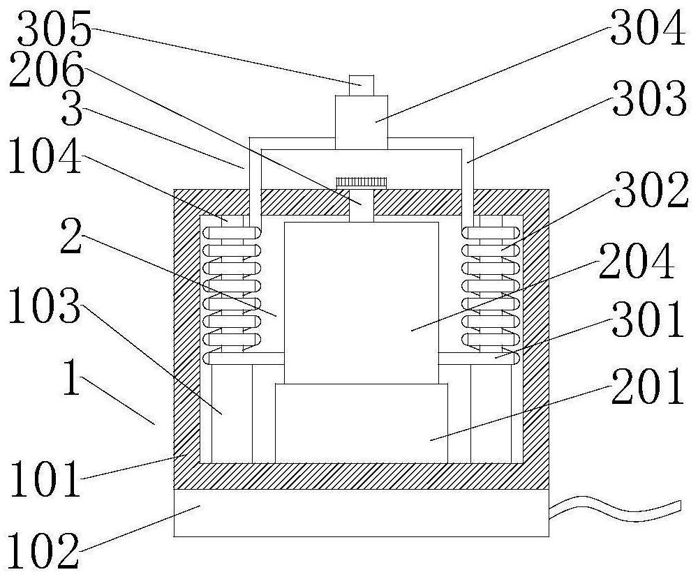
FIG. 1 is a cross-sectional view of the structure of the present invention;
FIG. 2 is a schematic view of the interior of the insulated housing of the present invention;
FIG. 3 is a schematic view of a steam generating drum according to the present invention;
FIG. 4 is a sectional view of the steam generating tub according to the present invention;
fig. 5 is a schematic view of a liquid storage barrel according to the present invention.
Wherein: 1. a protection mechanism; 101. a protective housing; 102. a power distribution chamber; 103. fixing the support rod; 104. a limiting rod; 2. a steam generating mechanism; 201. a heat-insulating shell; 202. a support cylinder; 203. a heating member; 204. a steam generation barrel; 205. fixing grooves; 206. a liquid feeding pipe; 207. a liquid storage barrel; 208. a vapor emission port; 209. drying the slices; 3. a kinetic energy transmission mechanism; 301. a connecting pipe; 302. winding the tube; 303. an output pipe; 304. a confluence pipe; 305. and a power external pipe.
Detailed Description
The technical solutions in the embodiments of the present invention will be clearly and completely described below with reference to the drawings in the embodiments of the present invention, and it is obvious that the described embodiments are only a part of the embodiments of the present invention, and not all of the embodiments. All other embodiments, which can be derived by a person skilled in the art from the embodiments given herein without making any creative effort, shall fall within the protection scope of the present invention.
Detailed description of the invention
The present embodiment is an embodiment of a steam generator based on energy-saving and environment-friendly technology.
Referring to fig. 1-5, the steam generating device based on energy-saving and environmental-friendly technology comprises a protection mechanism 1, wherein a steam generating mechanism 2 is fixedly connected inside the protection mechanism 1, and a kinetic energy transmission mechanism 3 is arranged inside the protection mechanism 1;
the protection mechanism 1 comprises a protection shell 101, wherein the bottom of the protection shell 101 is fixedly connected with a power distribution chamber 102, the inner bottom of the protection shell 101 is fixedly connected with a fixed support rod 103, and the upper end of the fixed support rod 103 is fixedly connected with a limiting rod 104;
the steam generating mechanism 2 comprises a heat-insulating shell 201, a supporting cylinder 202 is fixedly connected to the inner bottom wall of the heat-insulating shell 201, a heating component 203 is fixedly connected to the inside of the supporting cylinder 202, a steam generating barrel 204 is inserted into the heat-insulating shell 201, a fixing groove 205 is formed in the bottom of the steam generating barrel 204, a liquid adding pipe 206 is fixedly connected to the top of the steam generating barrel 204, a liquid storage barrel 207 is fixedly connected to the inside of the steam generating barrel 204, a steam emitting port 208 is formed in the top of the outer surface of the liquid storage barrel 207, and a drying sheet 209 is fixedly connected to the outer surface of the liquid storage barrel 207;
the kinetic energy transmission mechanism 3 comprises a connecting pipe 301, a winding pipe 302 is fixedly connected to the other end of the connecting pipe 301, an output pipe 303 is fixedly connected to the other end of the winding pipe 302, a junction pipe 304 is fixedly connected to the other end of the output pipe 303, and a power outer pipe 305 is fixedly connected to the upper end of the junction pipe 304.
Through the technical scheme, the steam generation barrel 204 is arranged, the liquid storage barrel 207 is arranged in the steam generation barrel 204, when the heating member 203 heats liquid to generate steam, the steam is discharged through the steam emitting port 208 and accumulated until the steam becomes mechanical power, and meanwhile, the steam coming out of the steam emitting port 208 is dried by the drying sheet 209, so that the humidity of water molecules in the steam is reduced, the steam is reduced and is condensed by the temperature difference of the winding pipe 302 in the transmission process to form water vapor, and the effect of reducing energy consumption is achieved;
set up two sets of winding pipes 302 and all be connected to the flow-joining pipe 304, when carrying out the steam energy supply, the inside comdenstion water of winding pipe 302 can flow back to the inside recycle of steam generation bucket 204, merges to flow-joining pipe 304 through many steam simultaneously to it is stronger to make steam power transmit for the transmission single tube, has reached water conservation, the stronger effect of power.
Specifically, a power supply control board is arranged inside the power distribution chamber 102, a power supply line of the power supply control board inside the power distribution chamber 102 extends to the inside of the heat preservation shell 201, and the fixed support rod 103 is located outside the heat preservation shell 201.
Through above-mentioned technical scheme, power distribution room 102 is used for protecting the power control board, supplies energy and control to heating member 203 through the power control board simultaneously, and fixed support rod 103 is used for supporting winding pipe 302, and wherein the power control board is current ripe power control device.
Specifically, the diameter of the limiting rod 104 is smaller than that of the fixed support rod 103, the upper end of the fixed support rod 103 is in lap joint with the lower end of the winding pipe 302, and the outer surface of the limiting rod 104 is in lap joint with the inner wall of the winding pipe 302.
Through the technical scheme, the limiting rod 104 can support and limit the winding pipe 302, and the fixed supporting rod 103 with the larger diameter is used for supporting the bottom of the winding pipe 302.
Specifically, the two ends of the heating member 203 are communicated with the power control board respectively, the outer surface of the heating member 203 is lapped with the lower end of the steam generation barrel 204, the upper end of the liquid feeding pipe 206 penetrates through the top of the protective casing 101 and is provided with a sealing cover, and a plurality of air holes are formed in the outer surface of the drying sheet 209.
Through above-mentioned technical scheme, heating member 203 is used for heating liquid to form steam and provide power for machinery, and liquid feeding pipe 206 is arranged in the convenience and adds liquid in the use, sets up simultaneously that dry piece 209 can absorb the moisture in the steam, thereby reduces the condensation effect.
Specifically, the connection pipe 301 is communicated with the steam generating barrel 204, the output pipe 303 penetrates through the top of the protective casing 101, and the confluence pipe 304 is communicated with all the output pipes 303.
Through the technical scheme, the steam generated in the steam generation barrel 204 is transmitted to the outside of the protective shell 101 through the connecting pipe 301, and is discharged outside through the power external pipe 305 for power supply.
When the steam generator is used, liquid is added through the liquid adding pipe 206, then the liquid adding pipe 206 is sealed, meanwhile, the power external pipe 305 is connected with a power pipeline, finally, the heating member 203 is electrified, the heating member 203 heats the liquid to generate steam, the generated steam is accumulated and pressurized inside the steam generating barrel 204 through the steam emitting port 208, the steam is dried by the drying sheets 209 during pressurization, and the steam is discharged through the connecting pipe 301 to provide power for machinery.
Detailed description of the invention
The embodiment is an embodiment of a key structure of a steam generating device based on an energy-saving and environment-friendly technology.
Energy-concerving and environment-protective technology-based steam generator's key structure, for protection machanism 1, protection machanism 1 includes protecting sheathing 101, and protecting sheathing 101 bottom fixedly connected with power distribution room 102, the interior bottom fixedly connected with fixed support rod 103 of protecting sheathing 101, the upper end fixedly connected with gag lever post 104 of fixed support rod 103.
Through the technical scheme, the whole device is protected by the protective casing 101, the power supply is controlled by components in the power distribution chamber 102, and the internal device is fixed and limited by the fixed support rod 103 and the limiting rod 104.
Detailed description of the invention
The embodiment is an embodiment of a key structure of a steam generating device based on an energy-saving and environment-friendly technology.
Steam generator's key structure based on energy-concerving and environment-protective technique, for steam generator 2, steam generator 2 includes lagging casing 201, wall fixedly connected with supporting cylinder 202 in lagging casing 201, the inside fixedly connected with heating member 203 of supporting cylinder 202, the inside grafting of lagging casing 201 has steam generator bucket 204, fixed slot 205 has been seted up to steam generator bucket 204's bottom, steam generator bucket 204's top fixedly connected with liquid feeding pipe 206, steam generator bucket 204's inside fixedly connected with liquid storage bucket 207, steam gives off mouthful 208 has been seted up at liquid storage bucket 207's surface top, liquid storage bucket 207's surface fixedly connected with drying sheet 209.
Through above-mentioned technical scheme, lagging casing 201 is used for keeping warm steam generator barrel 204 bottom to promote the energy efficiency of heating member 203, and filling pipe 206 is used for making things convenient for the interpolation of liquid, and liquid storage bucket 207 is used for making liquid and steam keep apart, in order to reduce the humidity of steam, and through the further dry steam of dry sheet 209.
Detailed description of the invention
The embodiment is an embodiment of a key structure of a steam generating device based on an energy-saving and environment-friendly technology.
Energy-concerving and environment-protective technique based steam generator's key structure, for kinetic energy transmission device 3, kinetic energy transmission device 3 includes connecting pipe 301, and connecting pipe 301's other end fixedly connected with winding pipe 302, winding pipe 302's other end fixedly connected with output tube 303, output tube 303's other end fixedly connected with flow tube 304 that closes, the outer pipe 305 of upper end fixedly connected with power of flow tube 304.
Through above-mentioned technical scheme, connecting pipe 301, winding pipe 302 and output tube 303 are used for outwards transmitting steam, and winding pipe 302 can increase the delivery distance of steam simultaneously to this pressure that increases steam, and can make the comdenstion water backward flow by reuse, and flow-joining pipe 304 can carry out the confluence with many places steam, thereby promotes power strength, and sets up power and take over 305 and conveniently be connected with mechanical equipment outward.
Although embodiments of the present invention have been shown and described, it will be appreciated by those skilled in the art that changes, modifications, substitutions and alterations can be made in these embodiments without departing from the principles and spirit of the invention, the scope of which is defined in the appended claims and their equivalents.
- 上一篇:一种医用注射器针头装配设备
- 下一篇:一种基于多热源耦合的热电联产系统及调节方法