Weaving equipment and weaving process of cation shading cloth
阅读说明:本技术 一种阳离子遮光布的纺织设备及织造工艺 (Weaving equipment and weaving process of cation shading cloth ) 是由 王栋诚 钱伟浩 徐磊 于 2021-06-26 设计创作,主要内容包括:本申请涉及纺织技术的领域,尤其是一种阳离子遮光布的纺织设备及织造工艺,解决了两组经线在上下往复移动时,易与相邻的经线发生摩擦,导致纤维磨损,影响纺织成品的质量的问题,其包括机体,所述机体上设置有用于传送经线的经轴以及用于引离成品布的卷辊,所述经轴和所述卷辊间设有用于分别带动两组经线上下移动并横向分离的分离机构,所述机体两侧于所述分离机构朝向卷辊的一面设有用于穿设纬线的引线机构,所述引线机构与所述分离机构间设有用于推动纬线的钢筘,所述引线机构朝向所述卷辊的一侧设有一组用于固定成品布的夹板。本申请具有减少经线间的摩擦,提高纺织时经线的质量的效果。(The utility model belongs to the technical field of the weaving technique and specifically relates to a weaving equipment and weaving technology of cation shading cloth has solved two sets of warps when reciprocating motion from top to bottom, easily takes place the friction with adjacent warp, leads to the fibre wearing and tearing, influences the problem of the finished product's of weaving quality, and it includes the organism, be provided with the roller that is used for conveying warp's warp beam and is used for leading from finished product cloth on the organism, the warp beam with be equipped with between the roller and be used for driving two sets of warps and reciprocate and lateral segregation's separating mechanism respectively, the organism both sides in separating mechanism is equipped with the lead wire mechanism who is used for wearing to establish weft towards the one side of roller, lead wire mechanism with be equipped with the reed that is used for promoting weft between separating mechanism, lead wire mechanism orientation one side of roller is equipped with a set of splint that are used for fixed finished product cloth. This application has the friction that reduces between the warp, the effect of warp's quality when improving the weaving.)
1. A weaving equipment of positive ion shading cloth which characterized in that: including organism (1), be provided with warp beam (2) that are used for conveying warp on organism (1) and be used for drawing from winding up roller (8) of finished product cloth, warp beam (2) with be equipped with between winding up roller (8) and be used for driving two sets of warp respectively and reciprocate and lateral separation's separating mechanism (3), organism (1) both sides in separating mechanism (3) are equipped with lead wire mechanism (5) that are used for wearing to establish weft towards the one side of winding up roller (8), lead wire mechanism (5) with be equipped with between separating mechanism (3) and be used for promoting weft reed (4), lead wire mechanism (5) orientation one side of winding up roller (8) is equipped with a set of splint (6) that are used for fixed finished product cloth.
2. The apparatus for spinning a cationic sunscreen cloth according to claim 1, wherein: separating mechanism (3) include two sets of heald wires (33) of vertical setting, each heald wire (33) all are connected with the spacing ring (331) that supplies warp to wear to establish, each heald wire (33) all are connected with spacing piece (332) of horizontal setting, and each spacing piece (332) all are connected with slide bar (333), separating mechanism (3) still include two sets of curved sliding groove (311), and every group slide groove (311) and be the form distribution of dispersing, each slide bar (333) all with corresponding sliding groove (311) cooperation of sliding, every group the spacing piece (332) are slided jointly and are set up in a carriage release lever (32), and each carriage release lever (32) all are connected with and are used for driving piece (323) that carriage release lever (32) reciprocated.
3. The apparatus for spinning a cationic sunscreen cloth according to claim 2, wherein: each sliding rod (333) is connected with the corresponding limiting sheet (332) in a fitting mode.
4. The apparatus for spinning a cationic sunscreen cloth according to claim 2, wherein: each the carriage release lever (32) inner wall all is equipped with a plurality of roller shafts (322), each spacing piece (332) all with corresponding roller shaft (322) are inconsistent.
5. The apparatus for spinning a cationic sunscreen cloth according to claim 2, wherein: each group of sliding grooves (311) is connected with a fixing plate (31) together.
6. The apparatus for spinning a cationic sunscreen cloth according to claim 5, wherein: each movable rod (32) both ends all are connected with pulley (321), and each fixed plate (31) both ends all are equipped with the confession correspondingly the spacing groove (312) that pulley (321) slided.
7. The apparatus for spinning a cationic sunscreen cloth according to claim 1, wherein: a plurality of warp feeding rolls (21) used for adjusting the tension degree of warp threads are arranged between the warp beam (2) and the separating mechanism (3).
8. The apparatus for spinning a cationic sunscreen cloth according to claim 7, wherein: the let-off roll is characterized in that torsion springs (22) are arranged in the let-off roll (21), and the tail ends of the torsion springs (22) are fixedly connected with the inner wall of the let-off roll (21).
9. The apparatus for spinning a cationic sunscreen cloth according to claim 1, wherein: and a heating roller (7) is arranged between the winding roller (8) and the separating mechanism (3).
10. A weaving process of a cation sunscreen cloth, which applies a weaving device of the cation sunscreen cloth of any one of claims 1 to 9, characterized in that: the method comprises the following steps:
step1, arranging a plurality of warps on a warp beam (2), arranging each warp on a separate warp feeding roll (21) respectively, and arranging the warps into corresponding limiting rings (331) respectively so that the warps are divided into two groups at intervals;
step2, leading a plurality of warps to a winding roller (8), starting the winding roller (8) to enable the warps to slowly move along the transmission direction, starting a driving piece (323) to enable one moving rod (32) to drive one group of heddles (33) to move upwards, enabling the other moving rod (32) to drive the other group of heddles (33) to move downwards, enabling the two groups of heddles (33) to be dispersed along the length direction of the moving rod (32) under the sliding fit of the sliding rod (333) and the sliding groove (311), enabling the two groups of the warps to respectively move upwards or downwards and to be dispersed along the length direction of the moving rod (32), and enabling the two groups of the warps to be separated and form a weaving opening;
step3, starting the thread leading mechanism (5), sending a weft thread from one side of the machine body (1) to the other side of the machine body (1) through the weaving opening, and taking the thread leading mechanism (5) away from the weaving opening area;
step4, starting the reed (4), pushing the weft threads penetrating through the weaving port to the direction close to the clamping plate (6), limiting the weft threads and the warp threads mutually, and resetting the reed (4);
step5, starting the driving part (323), enabling the two moving rods (32) to respectively drive the two groups of healds (33) to move reversely and drive the two groups of warps to move reversely, enabling the two groups of warps to clamp the former weft and form a weaving opening again;
and Step6, repeating the operation of starting the thread leading mechanism (5) and the driving part (323) to enable the weft threads to pass through two groups of warp threads one by one to form finished cloth with specified weft density, and winding the finished cloth onto a winding roller (8) after the finished cloth is softened and shaped by a heating roller (7).
Technical Field
The application relates to the field of textile technology, in particular to textile equipment and a weaving process of cation shading cloth.
Background
At present, natural fibers and artificial fibers are various in types and different in properties, and various different functions can be realized by adopting a proper fiber type and a proper textile process.
For example, products such as curtains and the like which need strong ultraviolet resistance can be made of cationic fabric, cationic polyester yarns are used as warp yarns, ordinary polyester yarns are used as weft yarns, and the cationic shading cloth is formed by interweaving the cationic polyester yarns and the weft yarns, so that the cationic shading cloth has strong light color fastness, is not easy to fade after being colored, and has better wear resistance and elasticity. When weaving, the warp is divided into two groups at intervals, the two groups of warp move up and down, the weft passing through the two groups of warp is clamped and fixed, and the weaving is repeated for many times, so that the fiber can be made into the fabric.
In view of the above-mentioned related technologies, the inventor believes that there is a defect that when two groups of warp yarns reciprocate up and down, the two groups of warp yarns are easy to rub against adjacent warp yarns, which causes fiber abrasion and affects the quality of a textile finished product.
Disclosure of Invention
In order to reduce friction among warps and improve the quality of the warps during weaving, the application provides weaving equipment and a weaving process of cation shading cloth.
In a first aspect, the application provides a textile apparatus for cation shading cloth, which adopts the following technical scheme:
the utility model provides a weaving equipment of cation shading cloth, includes the organism, be provided with the warp beam that is used for conveying warp on the organism and be used for drawing from the winding up roller of finished product cloth, the warp beam with be equipped with between the winding up roller and be used for driving two sets of warp respectively and reciprocate and lateral segregation's separating mechanism, the organism both sides in separating mechanism is equipped with the lead wire mechanism that is used for wearing to establish weft towards the one side of winding up roller, lead wire mechanism with be equipped with the reed that is used for promoting weft between separating mechanism, lead wire mechanism orientation one side of winding up roller is equipped with a set of splint that are used for fixed finished product cloth.
Through adopting above-mentioned technical scheme, it is two sets of about having made things convenient for to fall into warp through separating mechanism, wear to establish to two sets of warp between with weft through the lead mechanism, push warp to the intersection of two sets of warps through the reed, and make warp and weft form the specified weft density, it is spacing to press from both sides finished product cloth through splint, roll up finished product cloth gradually through the winding up roller, made things convenient for warp and weft to finished product cloth's preparation, and when separating mechanism reciprocated warp, with warp along horizontal dispersion, the friction between the warp when having reduced warp and removing, prevent that warp from rubbing repeatedly and leading to warp wearing and tearing, textile quality has been improved.
Optionally, the separating mechanism includes two sets of vertically arranged heddles, each heddle is connected with a limiting ring for warp threads to penetrate, each heddle is connected with a transversely arranged limiting piece, each limiting piece is connected with a sliding rod, the separating mechanism further includes two sets of arc-shaped sliding grooves, each sliding groove is distributed in a diverging manner, each sliding rod is in sliding fit with the corresponding sliding groove, each limiting piece is arranged in one moving rod in a sliding manner, and each moving rod is connected with a driving piece for driving the moving rod to move up and down.
Through adopting above-mentioned technical scheme, made things convenient for the carriage release lever to drive a set of harness wire and reciprocated, and drive the slide bar and slide at the inslot that slides, automatic lateral shifting when having made things convenient for the harness wire to reciprocate, automatic dispersion when having realized two sets of warp alternate segregation, prevent that two sets of warp from rubbing each other when reciprocating, spacing piece through fixed connection horizontal setting on the harness wire, and set up the carriage release lever outside spacing piece, made things convenient for and kept the vertical of harness wire through the horizontal slip of spacing piece in the carriage release lever, take place dislocation and extrusion when preventing two sets of harness wires from reciprocating, lead to the tying a knot or the friction each other of warp.
Optionally, each sliding rod is connected with the corresponding limiting piece in a jogged mode.
Through adopting above-mentioned technical scheme for when the pole that slides at the inslot that slides, the sliding friction between pole and the groove that slides changes into rolling friction, has reduced the mutual friction between pole and the groove that slides, has made things convenient for the pole that slides in the groove that slides.
Optionally, each of the inner walls of the moving rods is provided with a plurality of rollers, and each of the limiting pieces is abutted against the corresponding roller.
Through adopting above-mentioned technical scheme, change the sliding friction between carriage release lever inner wall and spacing piece into rolling friction, reduced the mutual friction between carriage release lever and spacing piece, made things convenient for the slip of spacing piece in the carriage release lever.
Optionally, each group of sliding grooves is connected with a fixing plate.
Through adopting above-mentioned technical scheme, reduced the vibrations of the pole that slides at the inslot that slides, improved the stability of pole that slides at the inslot that slides, made things convenient for the pole that slides at the inslot that slides.
Optionally, each carriage release lever both ends all are connected with the pulley, and each fixed plate both ends all are equipped with the confession correspondingly the spacing groove that the pulley slided.
Through adopting above-mentioned technical scheme, improved the stability when the carriage release lever reciprocates to and the stability of slide bar when the inslot that slides removes, prevent that the carriage release lever from deviating predetermined moving direction.
Optionally, a plurality of warp feeding rolls for adjusting the tension of warp threads are arranged between the warp beam and the separating mechanism.
Through adopting above-mentioned technical scheme, made things convenient for warp to be driven when reciprocating with warp's rate of tension to maintain in certain extent, prevented that warp from crossing the pine and leading to finished product cloth fiber density uneven, improved the overall quality of finished product cloth.
Optionally, the warp feeding rolls are internally provided with torsion springs, and the tail ends of the torsion springs are fixedly connected with the inner walls of the corresponding warp feeding rolls.
Through adopting above-mentioned technical scheme for let-off roll always has the trend of warp to warp axle direction conveying under the torsional spring effect, made things convenient for the warp of the extra length that stretches out from the warp axle when will keeping away from each other to warp axle direction rolling, in order to maintain the rate of tension of warp, guaranteed the even stability of the fiber density of finished product cloth.
Optionally, a heating roller is arranged between the winding roller and the separating mechanism.
By adopting the technical scheme, finished cloth woven by warps and wefts can be conveniently ironed and shaped, and the textile processing quality of the finished cloth is further improved.
In a second aspect, the present application provides a weaving process of a cationic black-out fabric, comprising the following steps:
step1, arranging a plurality of warps on a warp beam, arranging each warp on a separate warp feeding roll respectively, and arranging the warps in corresponding limiting rings respectively in a penetrating manner, so that the warps are divided into two groups at intervals;
step2, leading a plurality of warps to a winding roller, starting the winding roller to enable the warps to slowly move along the transmission direction, starting a driving piece to enable one moving rod to drive one group of heddles to move upwards, and enabling the other moving rod to drive the other group of heddles to move downwards, wherein under the sliding fit of the sliding rod and the sliding groove, the two groups of heddles are dispersed along the length direction of the moving rod, so that the two groups of warps respectively move upwards or downwards and are dispersed along the length direction of the moving rod, and the two groups of warps are separated to form a weaving opening;
step3, starting a thread leading mechanism, sending a weft thread from one side of the machine body to the other side of the machine body through the weaving opening, and taking the thread leading mechanism away from the weaving opening area;
step4, starting the reed, pushing the weft threads penetrating through the weaving port to the direction close to the clamping plate, limiting the weft threads and the warp threads mutually, and resetting the reed;
step5, starting the driving piece, enabling the two moving rods to respectively drive the two groups of heddles to move reversely, and driving the two groups of warps to move reversely, enabling the two groups of warps to clamp the former weft and form a weaving opening again;
and Step6, repeating the operation of starting the thread leading mechanism and the driving part to enable the weft threads to pass through two groups of warp threads one by one to form finished cloth with specified weft density, and winding the finished cloth onto a winding roller after the finished cloth is softened and shaped by a heating roller.
By adopting the technical scheme, the warps are conveyed into the limiting ring through the warp beam, the heald wire is driven to move up and down through the moving rod, the two groups of warps are driven to alternately form a weaving opening, the wefts are fed into the weaving opening through the thread leading mechanism, the wefts are pushed to the intersection of the two groups of warps through the reed, the alternate penetration and weaving of the wefts and the warps are facilitated, the sliding rod is connected to the heald wire, the sliding groove for the sliding rod to slide is arranged, the automatic dispersion of the heald wire during the up-and-down movement is facilitated, the mutual friction among the warps is reduced, the transverse limiting sheet is fixedly connected to the heald wire, the moving rod for the transverse sliding of the limiting sheet is arranged, the vertical stability of the heald wire during the transverse movement is facilitated, the dislocation among the heald wires is prevented, the stability and the tensioning of the woven part are ensured when the wefts are woven inwards woven through the arrangement of the clamping plate, the woven part is ironed and shaped through the heating roller, the textile quality of the finished cloth is improved, the finished cloth is rolled through the rolling roller, and the continuous unwinding of warps and the continuous textile of the finished cloth are facilitated.
In summary, the present application includes at least one of the following beneficial technical effects:
1. the warp is conveniently divided into an upper group and a lower group by the separating mechanism, the weft is inserted between the two groups of warps by the thread leading mechanism, the warp is pushed to the intersection of the two groups of warps by the reed, the warp and the weft form a specified weft density, the finished cloth is clamped and limited by the clamping plate, and the finished cloth is gradually wound by the winding roller, so that the warp and the weft are conveniently made to the finished cloth, the warp is transversely dispersed while the separating mechanism moves the warp up and down, the friction between the warps is reduced when the warp moves, the warp abrasion caused by repeated friction is prevented, and the textile quality is improved;
2. the sliding rod is connected with the limiting piece in an embedded mode, and the rolling shaft is arranged in the moving rod, so that the sliding of the sliding rod in the sliding groove and the sliding of the limiting piece in the moving rod are facilitated, the friction between the sliding rod and the sliding groove and the friction between the limiting piece and the moving rod are reduced, and the healds are convenient to transversely disperse or gather when moving up and down;
3. through set up the let-off book between warp beam and separating mechanism, made things convenient for through the tendency of let-off book to warp beam conveying warp to guarantee every warp rate of tension, prevent that warp from crossing the pine and leading to the flaw to appear in the finished product cloth after the weaving.
Drawings
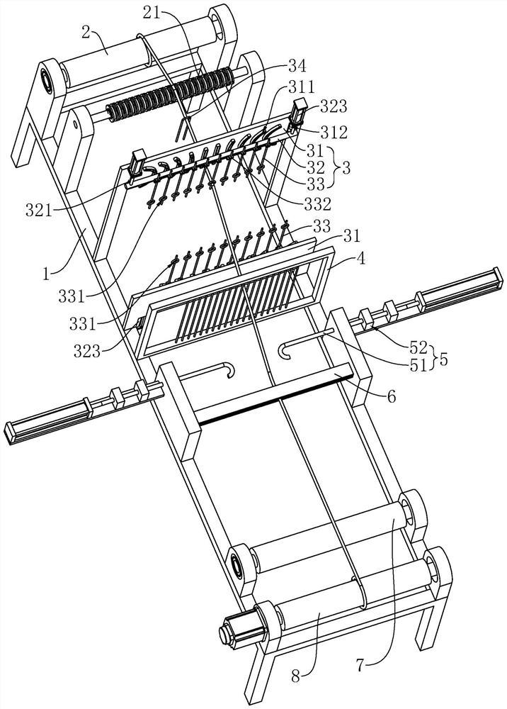
Fig. 1 is a schematic structural view of a weaving device of a cation light-screening cloth according to an embodiment of the present application.
Fig. 2 is a schematic structural diagram of a separation mechanism of a weaving device of a cation light-shielding cloth according to an embodiment of the present application.
Description of reference numerals: 1. a body; 2. a warp beam; 21. sending warp rolls; 22. a torsion spring; 3. a separating mechanism; 31. a fixing plate; 311. a sliding groove; 312. a limiting groove; 32. a travel bar; 321. a pulley; 322. a roller; 323. a drive member; 33. a harness cord; 331. a limiting ring; 332. a limiting sheet; 333. a slide bar; 34. a dropper; 4. a reed; 5. a wire-leading mechanism; 51. a rapier; 52. a guide rail; 6. a splint; 7. a heating roller; 8. and (4) winding the roller.
Detailed Description
The present application is described in further detail below with reference to figures 1-2.
Example (b):
the embodiment of the application discloses weaving equipment of cation shading cloth. Referring to fig. 1 and 2, a weaving equipment of cation shading cloth, including organism 1, 1 both ends of organism are equipped with warp beam 2 and the winding up roller 8 of rolling up finished product cloth that is used for conveying warp respectively, and warp is conveyed to winding up roller 8 by warp beam 2, is equipped with separating mechanism 3 behind warp beam 2, and separating mechanism 3 includes two fixed plates 31, and each fixed plate 31 one side all is equipped with a plurality of curved sliding groove 311 by the middle part to both ends along the horizontal direction, and sliding groove 311 on each fixed plate 31 all is the form of dispersing and distributes.
Referring to fig. 1 and 2, a moving rod 32 is horizontally disposed on one side of each fixing plate 31 corresponding to the sliding groove 311, a plurality of limiting pieces 332 are horizontally slidably disposed in the moving rod 32, one end of each limiting piece 332 is connected with a vertically-arranged heddle 33, the other end of each limiting piece 332 is connected with a sliding rod 333 in an embedded manner, the sliding rods 333 correspond to the sliding grooves 311 one by one, a driving member 323 for driving the moving rod 32 to move in the vertical direction is connected to the moving rod 32, the driving member 323 can be an air cylinder in the embodiment of the present application, when the moving rod 32 moves up and down, each sliding rod 333 is driven to slide in the corresponding sliding groove 311 and drives the corresponding limiting piece 332 to slide in the moving rod 32, and the automatic movement in the horizontal direction while the heddle 33 moves up and down is facilitated. The inner wall of the moving rod 32 is provided with the plurality of rolling shafts 322, the side walls of the rolling shafts 322 are abutted against the side walls of the limiting pieces 332, so that the sliding of the limiting pieces 332 in the moving rod 32 is facilitated, and the abrasion of the limiting pieces 332 in the moving rod 32 during sliding is reduced.
Referring to fig. 1 and 2, each heddle 33 is connected with a limiting ring 331, each limiting ring 331 is provided with a warp thread, and two adjacent warp threads of each warp thread are provided with a corresponding limiting ring 331 of another fixing plate 31, so that when the movable rod 32 drives a plurality of heddles 33 to move, a group of warp threads corresponding to the same fixing plate 31 are driven to move, and the two groups of warp threads corresponding to the two fixing plates 31 are separated from each other.
Referring to fig. 1 and 2, two ends of each moving rod 32 are connected with a pulley 321, and each fixing plate 31 is provided with a limiting groove 312 for the pulley 321 to slide, so that the moving rod 32 can move more stably on one side of the fixing plate 31, and the moving direction of the moving rod 32 is prevented from deviating.
Referring to fig. 1 and 2, the two sides of the machine body 1 are provided with the thread leading mechanism 5 on one side of the fixing plate 31 facing the winding roller 8, the thread leading mechanism 5 comprises two matched rapier 51, a guide rail 52 for the rapier 51 to slide transversely is arranged between each rapier 51 and the machine body 1, when two groups of warps are far away from each other and form a weaving opening at the intersection, one rapier 51 sends the weft to the center of the weaving opening from one side of the machine body 1, and another rapier 51 leads the weft to the other side of the machine body 1, thereby facilitating the threading of the weft between the two groups of warps.
Referring to fig. 1 and 2, a reed 4 is arranged between the separating mechanism 3 and the thread leading mechanism 5, a plurality of round rods are arranged on the reed 4 along the vertical direction, each warp thread penetrates through the two adjacent round rods, when the weft thread is fed into the weaving opening, the reed 4 moves towards the direction close to the crossing position of the two groups of warp threads and pushes the weft thread to the crossing position of the two groups of warp threads, so that the weft thread reaches the specified weft density, and the spacing and the weaving of the two groups of warp threads and the weft thread are facilitated.
Referring to fig. 1 and 2, one side of the reed 4, away from the intersection of the two groups of warps, is provided with a group of clamping plates 6, and the clamping plates 6 clamp the flat cloth formed by alternately weaving the warps and the wefts, so that the situation that the two groups of warps shake when the wefts are woven between the two groups of warps to cause weft displacement and influence the quality of the finished cloth is prevented.
Referring to fig. 1 and 2, one side of the winding roller 8, which is close to the clamping plate 6, is provided with a heating roller 7, the finished cloth is erected on the heating roller 7, and the heating roller 7 is used for ironing and shaping the finished cloth, so that the quality of the finished cloth is improved, and the winding roller 8 is convenient for subsequent storage of the finished cloth.
Referring to fig. 1 and 2, be equipped with a plurality of let-off rolls 21 between warp beam 2 and separating mechanism 3, each let-off roll 21 goes up to convolute a warp respectively, all be equipped with a torsional spring 22 in each let-off roll 21, the torsional spring 22 end all is connected to corresponding let-off roll 21 inner wall, a plurality of torsional springs 22 centers are connected to a horizontal pole jointly, make torsional spring 22 and let-off roll 21 always have the trend of conveying the warp to the direction of keeping away from separating mechanism 3, the rate of tension of having made things convenient for to keep each warp, prevent that warp from leading to partial warp to relax because of the tensile length difference when reciprocating motion from top to bottom, the fiber density when influencing warp weaving.
Referring to fig. 1 and 2, each warp stop sheet 34 is hung on each warp, and when the warp is broken, the warp stop sheets 34 fall from the warp onto the machine body 1 below, and the machine body 1 is stopped in time, so that the warp is conveniently reconnected when the warp is broken and lost, and the quality defect of the finished cloth caused by the warp loss is prevented.
The implementation principle of the textile equipment of the cation shading cloth in the embodiment of the application is as follows: a plurality of warps are sequentially wound on a let-off roll 21 along the conveying direction of a warp beam 2 to a winding roller 8, penetrate through a limiting ring 331, penetrate through a reed 4, are arranged on a heating roller 7 and are wound on the winding roller 8, two moving rods 32 respectively drive two groups of warps to be close to or far away from each other, so that a weaving opening is formed at the intersection of the two groups of warps, a thread leading mechanism 5 sends wefts into the weaving opening, the reed 4 pushes wefts to the intersection of the two groups of warps, so that adjacent wefts form a specified weft density, the two moving rods 32 are reversely moved, so that the two groups of warps are crossed again to form the weaving opening, the former weft is clamped and fixed for multiple times, a section of finished fabric is formed, under the winding action of the winding roller 8, the woven finished fabric moves to the winding roller 8 and is wound by the winding roller 8 after being ironed and shaped by the heating roller 7.
The embodiment of the application also discloses a weaving process of the cation shading cloth, which comprises the following steps:
step1, arranging a plurality of warps on the warp beam 2, arranging each warp on the separate warp feeding roll 21, and arranging the warps into the corresponding limiting rings 331 respectively, so that the warps are divided into two groups at intervals;
step2, leading a plurality of warps to the winding roller 8, starting the winding roller 8 to enable the warps to slowly move along the transmission direction, starting the driving part 323 to enable one moving rod 32 to drive one group of heald wires 33 to move upwards, enabling the other moving rod 32 to drive the other group of heald wires 33 to move downwards, enabling the two groups of heald wires 33 to be dispersed along the length direction of the moving rod 32 under the sliding fit of the sliding rod 333 and the sliding groove 311, enabling the two groups of warps to move upwards or downwards respectively and to be dispersed along the length direction of the moving rod 32, and enabling the two groups of warps to be separated and form a weaving opening;
step3, starting the thread leading mechanism 5, sending a weft thread from one side of the machine body 1 to the other side of the machine body 1 through the weaving opening, and taking the thread leading mechanism 5 away from the weaving opening area;
step4, starting the reed 4, pushing the weft threads penetrating through the weaving port to the direction close to the clamping plate 6, limiting the weft threads and the warp threads mutually, and resetting the reed 4;
step5, starting the driving part 323, so that the two moving rods 32 respectively drive the two groups of heddles 33 to move reversely and drive the two groups of warps to move reversely, so that the two groups of warps clamp the former weft and form a weaving opening again;
and Step6, repeating the operation of starting the thread leading mechanism 5 and the driving part 323, enabling the weft threads to pass through two groups of warp threads one by one to form finished cloth with specified weft density, and winding the finished cloth onto a winding roller 8 after the finished cloth is softened and shaped by a heating roller 7.
The above is a preferred embodiment of the present application, and the scope of protection of the present application is not limited by the above, so: all equivalent changes made according to the structure, shape and principle of the present application shall be covered by the protection scope of the present application.
- 上一篇:一种医用注射器针头装配设备
- 下一篇:一种便于拆卸的纺织用的纺织辊